
New Launch Controller
Quote from Eric Becher on February 22, 2024, 11:23 pmI suppose I can print one on vinyl small enough for the sides of the box. But maybe we should "let" Brian finish building the thing before we sticker the crap out of it. 😄
I suppose I can print one on vinyl small enough for the sides of the box. But maybe we should "let" Brian finish building the thing before we sticker the crap out of it. 😄
Quote from Admin on February 23, 2024, 9:05 pmI can NOT say this enough or loud enough. THANK YOU Jeff Myers!!!
Jeff offered to cut the panel which I purchased for the new launch controller with his CNC machine. I went to his home this afternoon with the panel and its mockup. Jeff was provided with DXF files generated from my design software. He pulled the DXF into his CNC software and massaged some bits. The cutting was easy. The time was spent trying to make the panel level and stable in the CNC. It also didn't help that I brought everything to his home but the panel itself. 🙄🙄🙄Fortunately, my second oldest son was available to drive it up Jeff's home.
After the panel was cut, I got a tour of the observatory. Way cool! I'd love to spend an evening with Jeff sometime when he's observing the heavens.
Anyway, here's a brief video of the panel perparation.
https://youtu.be/Ov073okNZdg
I can NOT say this enough or loud enough. THANK YOU Jeff Myers!!!
Jeff offered to cut the panel which I purchased for the new launch controller with his CNC machine. I went to his home this afternoon with the panel and its mockup. Jeff was provided with DXF files generated from my design software. He pulled the DXF into his CNC software and massaged some bits. The cutting was easy. The time was spent trying to make the panel level and stable in the CNC. It also didn't help that I brought everything to his home but the panel itself. 🙄🙄🙄Fortunately, my second oldest son was available to drive it up Jeff's home.
After the panel was cut, I got a tour of the observatory. Way cool! I'd love to spend an evening with Jeff sometime when he's observing the heavens.
Anyway, here's a brief video of the panel perparation.
Quote from Ken Golomb on February 26, 2024, 5:54 pmIt looks like you might be able to get DOOM running on this launch controller.
Completely over-engineered as expected!! 😆
It looks like you might be able to get DOOM running on this launch controller.
Completely over-engineered as expected!! 😆
Quote from Admin on February 26, 2024, 7:08 pmQuote from Ken Golomb on February 26, 2024, 5:54 pmIt looks like you might be able to get DOOM running on this launch controller.
Completely over-engineered as expected!! 😆
Leave the DOOM for the wankers at InfoAge. 😉
I've populated the panel and today, I cut the rear apron for the connector/jacks. I have one more thing to do to the case but I was interrupted by a customer who picked up some files.
"Life is What Happens To You While You're Busy Making Other Plans" — John Lennon
"Work is What Happens To You While You're Busy Making Launch Controller" — Me
I now need to laser cut a a test fit for the rocker switch lugs to insure the placement is correct. Then, I do a deep dive into the schematic editor and PCB layout tools.
Quote from Ken Golomb on February 26, 2024, 5:54 pmIt looks like you might be able to get DOOM running on this launch controller.
Completely over-engineered as expected!! 😆
Leave the DOOM for the wankers at InfoAge. 😉
I've populated the panel and today, I cut the rear apron for the connector/jacks. I have one more thing to do to the case but I was interrupted by a customer who picked up some files.
"Life is What Happens To You While You're Busy Making Other Plans" — John Lennon
"Work is What Happens To You While You're Busy Making Launch Controller" — Me
I now need to laser cut a a test fit for the rocker switch lugs to insure the placement is correct. Then, I do a deep dive into the schematic editor and PCB layout tools.
Quote from Admin on March 20, 2024, 5:55 pmI've been busy trying to nail down all of the doctoring OKs I'll need for surgery next Tuesday, so my efforts on the Launch Controller have been waylaid. However, I have gotten most of the controller modeled up in KiCad (schematic, PCB layout, etc.).
I wanted to breadboard some of the logic to insure that it works but there's quite a lag time on getting some of the ICs from China. One set of ICs I ordered won't be here until April. That's unacceptable, so I made some modifications to the logic because I found a source for a similar IC on, believe it or not, Amazon with a two day delivery. These ICs just arrived and I plugged them in and wired them up on the breadboard. Actually, because of the delay in shipment from China, I was able to pare the IC count down by one IC!
I found that there was a way to incorporate the .DXF files from the layout and design of the Launch Control panel into KiCad, so now I need to find a way to output the PCB layout in such a fashion that I can laser cut a piece of cardboard to test fit the drilling mask against the actual populated Launch Control panel switches.
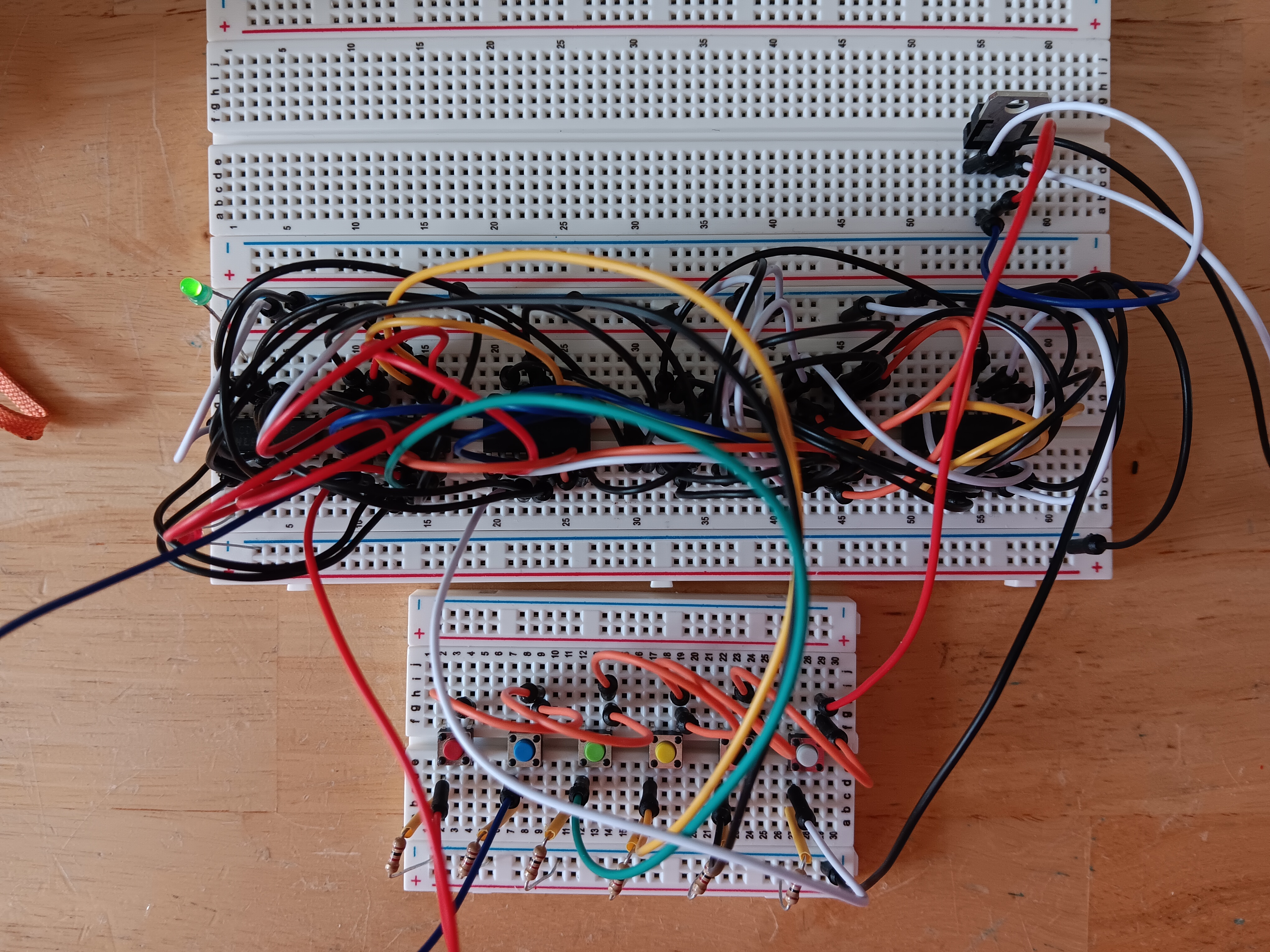
Here's a photo of the breadboarded logic circuit. There will be four of this circuit for each switch bank. Of course, I only need to breadboard and test one circuit.
I've been busy trying to nail down all of the doctoring OKs I'll need for surgery next Tuesday, so my efforts on the Launch Controller have been waylaid. However, I have gotten most of the controller modeled up in KiCad (schematic, PCB layout, etc.).
I wanted to breadboard some of the logic to insure that it works but there's quite a lag time on getting some of the ICs from China. One set of ICs I ordered won't be here until April. That's unacceptable, so I made some modifications to the logic because I found a source for a similar IC on, believe it or not, Amazon with a two day delivery. These ICs just arrived and I plugged them in and wired them up on the breadboard. Actually, because of the delay in shipment from China, I was able to pare the IC count down by one IC!
I found that there was a way to incorporate the .DXF files from the layout and design of the Launch Control panel into KiCad, so now I need to find a way to output the PCB layout in such a fashion that I can laser cut a piece of cardboard to test fit the drilling mask against the actual populated Launch Control panel switches.
Here's a photo of the breadboarded logic circuit. There will be four of this circuit for each switch bank. Of course, I only need to breadboard and test one circuit.
Uploaded files:
Quote from Ckirlew on March 20, 2024, 6:30 pmThe red wire needs to swap with the black one, or is that dark blue?
Can't wait for the finished product.
The red wire needs to swap with the black one, or is that dark blue?
Can't wait for the finished product.
Quote from Admin on March 20, 2024, 6:55 pmQuote from Ckirlew on March 20, 2024, 6:30 pmThe red wire needs to swap with the black one, or is that dark blue?
Can't wait for the finished product.
Well, if the doctoring gets sorted, I should have a week of recovery time to keep focused. I'm hoping I'll be able to travel for the Eclipse but at the rate things are happening here, I may need to forego the second celestial show of a lifetime.
Quote from Ckirlew on March 20, 2024, 6:30 pmThe red wire needs to swap with the black one, or is that dark blue?
Can't wait for the finished product.
Well, if the doctoring gets sorted, I should have a week of recovery time to keep focused. I'm hoping I'll be able to travel for the Eclipse but at the rate things are happening here, I may need to forego the second celestial show of a lifetime.
Quote from Admin on January 29, 2026, 5:52 pmWell, it's been some time since I've updated this thread.
There's been a push to get back to the new launch controller. The old units, I've been informed, now have some new wiring which should, hopefully, help alleviate some of the issues we've had with them.
I have spent the past days finalizing the new controller lockout logic. This is necessary to insure that with all of its new controls and switches, things (switches) are not just haphazardly switched on or off. I'll be finalizing the schematics and then, laying out the PCB boards for production. I hope to get this finalized this weekend so that I can send the Gerber files out for production.
I was working on this last weekend between the snowfall and all of the shoveling thereof. I know now that I need to be well focused when I'm doing this stuff as I inadvertently put one IC in backward and when I powered up the breadboards, the proverbial magic black smoke, which makes all electronics function, was allowed to escape. I had to wait for a refresh delivery from DigiKey Electronics to continue.
Anyway, here's what I'd setup and proved out today.
The larger breadboard has little more than switches to act as a small mock-up of the launch controller panel. It's easier than having the large front panel of the controller and myriad cables just to test some circuitry.
Well, it's been some time since I've updated this thread.
There's been a push to get back to the new launch controller. The old units, I've been informed, now have some new wiring which should, hopefully, help alleviate some of the issues we've had with them.
I have spent the past days finalizing the new controller lockout logic. This is necessary to insure that with all of its new controls and switches, things (switches) are not just haphazardly switched on or off. I'll be finalizing the schematics and then, laying out the PCB boards for production. I hope to get this finalized this weekend so that I can send the Gerber files out for production.
I was working on this last weekend between the snowfall and all of the shoveling thereof. I know now that I need to be well focused when I'm doing this stuff as I inadvertently put one IC in backward and when I powered up the breadboards, the proverbial magic black smoke, which makes all electronics function, was allowed to escape. I had to wait for a refresh delivery from DigiKey Electronics to continue.
Anyway, here's what I'd setup and proved out today.
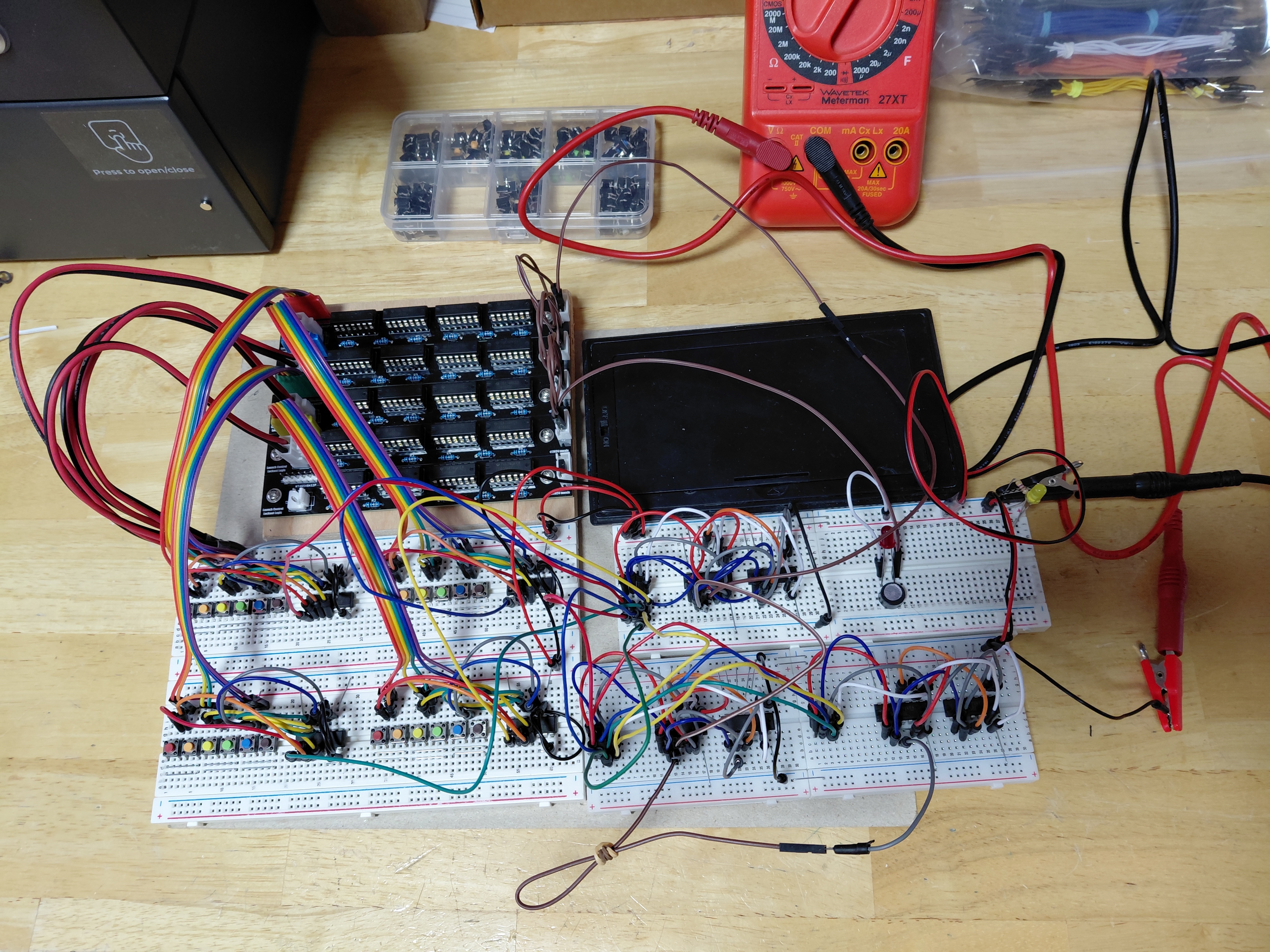
The larger breadboard has little more than switches to act as a small mock-up of the launch controller panel. It's easier than having the large front panel of the controller and myriad cables just to test some circuitry.
Uploaded files:
Quote from Admin on February 9, 2026, 5:11 pmQuote from Admin on January 29, 2026, 5:52 pmWell, it's been some time since I've updated this thread.
There's been a push to get back to the new launch controller. The old units, I've been informed, now have some new wiring which should, hopefully, help alleviate some of the issues we've had with them.
I have spent the past days finalizing the new controller lockout logic. This is necessary to insure that with all of its new controls and switches, things (switches) are not just haphazardly switched on or off. I'll be finalizing the schematics and then, laying out the PCB boards for production. I hope to get this finalized this weekend so that I can send the Gerber files out for production.
Well, as fate would have it, I received the new PCBs last Friday and I populated the boards. However, when I supplied power there was nothing. Happily, I had my digital multimeter in the loop measuring current and the meter went into overload. WTF? It turned out that I accidentally added a wire connection when I repositioned some traces on the circuit schematic with caused a connection between the two power busses. Grrr. I spent my Sunday morning unsoldering all of the components from the boards. About 140 solder points each. Happily, I'd ordered a new soldering station iwht very nice temperature control for the soldering iron and hot air rework pencil. The hot air pencil, set to 630ºF, made removal of the components a breeze.
I fixed the faux pas short and then recreated the PCB. I check each net carefully before generating the Gerber files for production. I sent them out on Saturday and in less than a day the boards were manufactured. They're in DHL hands now. I should have them by week's end. The price for five boards is $5.45 or $1.09 per board. Tariffs and taxes added $2.45 to the order. The biggest cost is in the shipping.
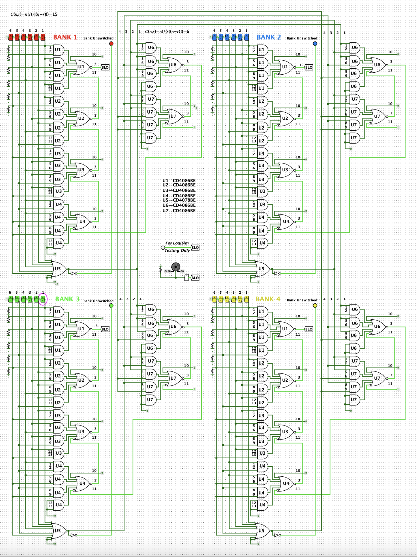
While I am waiting, I modeled the logic involved in LogiSim. This is a free logic modeling and simulation engine. Sort of a like breadboarding on the computer. I'd worked for 5+ years at the Naval Air Engineering Center creating such a program for the Navy which also did concurrent fault simulation to generate DATPG (Digital Automated Test Program Generation) that was used for actual testing and repair of avionics out on the Navy's carrier fleet. LogiSim only provides modeling and simulation.
Here's a print of the Lockout Logic for the launch controller from LogiSim.
Quote from Admin on January 29, 2026, 5:52 pmWell, it's been some time since I've updated this thread.
There's been a push to get back to the new launch controller. The old units, I've been informed, now have some new wiring which should, hopefully, help alleviate some of the issues we've had with them.
I have spent the past days finalizing the new controller lockout logic. This is necessary to insure that with all of its new controls and switches, things (switches) are not just haphazardly switched on or off. I'll be finalizing the schematics and then, laying out the PCB boards for production. I hope to get this finalized this weekend so that I can send the Gerber files out for production.
Well, as fate would have it, I received the new PCBs last Friday and I populated the boards. However, when I supplied power there was nothing. Happily, I had my digital multimeter in the loop measuring current and the meter went into overload. WTF? It turned out that I accidentally added a wire connection when I repositioned some traces on the circuit schematic with caused a connection between the two power busses. Grrr. I spent my Sunday morning unsoldering all of the components from the boards. About 140 solder points each. Happily, I'd ordered a new soldering station iwht very nice temperature control for the soldering iron and hot air rework pencil. The hot air pencil, set to 630ºF, made removal of the components a breeze.
I fixed the faux pas short and then recreated the PCB. I check each net carefully before generating the Gerber files for production. I sent them out on Saturday and in less than a day the boards were manufactured. They're in DHL hands now. I should have them by week's end. The price for five boards is $5.45 or $1.09 per board. Tariffs and taxes added $2.45 to the order. The biggest cost is in the shipping.
While I am waiting, I modeled the logic involved in LogiSim. This is a free logic modeling and simulation engine. Sort of a like breadboarding on the computer. I'd worked for 5+ years at the Naval Air Engineering Center creating such a program for the Navy which also did concurrent fault simulation to generate DATPG (Digital Automated Test Program Generation) that was used for actual testing and repair of avionics out on the Navy's carrier fleet. LogiSim only provides modeling and simulation.
Here's a print of the Lockout Logic for the launch controller from LogiSim.
Quote from Admin on February 9, 2026, 5:38 pmA little math for you because I love math.
Each bank of pad switches numbers six (6). To insure that only one switch is selected for continuity testing, anything two or more should cause a lockout. Therefore six switches has a total number of combinations of fifteen.
𝐶(𝑛,𝑟)=𝑛!/(𝑟!(𝑛−𝑟)!) — 𝐶(6,2)=6!(2!(6−2)!) = 15
I was able to do this with four quad-dual-input AOI (AND-OR-INVERTER) chips and one AND is not used. However, to do the same with all 24 switches would have been enormous.
𝐶(𝑛,𝑟)=𝑛!/(𝑟!(𝑛−𝑟)!) — 𝐶(24,2)=24!(2!(24−2)!) = 276
Doing the same combinatorial scheme as done for the initial six switches would have meant 69 AOI ICs!!!
With some careful consideration, I accomplished this with only 7 ICs per bank or 28 ICs total. That's a savings of 45 ICs!!!
A little math for you because I love math.
Each bank of pad switches numbers six (6). To insure that only one switch is selected for continuity testing, anything two or more should cause a lockout. Therefore six switches has a total number of combinations of fifteen.
𝐶(𝑛,𝑟)=𝑛!/(𝑟!(𝑛−𝑟)!) — 𝐶(6,2)=6!(2!(6−2)!) = 15
I was able to do this with four quad-dual-input AOI (AND-OR-INVERTER) chips and one AND is not used. However, to do the same with all 24 switches would have been enormous.
𝐶(𝑛,𝑟)=𝑛!/(𝑟!(𝑛−𝑟)!) — 𝐶(24,2)=24!(2!(24−2)!) = 276
Doing the same combinatorial scheme as done for the initial six switches would have meant 69 AOI ICs!!!
With some careful consideration, I accomplished this with only 7 ICs per bank or 28 ICs total. That's a savings of 45 ICs!!!