New Launch Controller
Quote from Admin on February 2, 2024, 9:07 pmIf I recall correctly, I showed off a metal panel case that I purchased to make a new club launch controller at the November launch. I was hoping Mohave the project further along but the holidays and aftermath have cause many problems with getting parts delivered. Several purchased went missing ins shipping and I had to go through hell to get them resupplied. In fact, I was supposed to have eight (8) shipments today; only two arrived and the rest are listed dallied in shipping … again.
Today, I receive the switches to enable the pads. Sadly, they were accompanied with a link to only rudimentary engineering dimensional drawing; not CAD file (STEP). Now only that but after pulling out the calipers to confirm the drawings, I found they were wrong too. I spent a goodly amount of time today developing a model of the switches to produce STEP files that can drive the rest of the design.
I also received a large (18in × 12in) copper clad phenolic board that will become the PCB for the controller. All switches, connectors, logic, etc. will be handled by a PCB with headers to connect to some of the external physical interfaces. A quart of PCB etchant also arrived today.
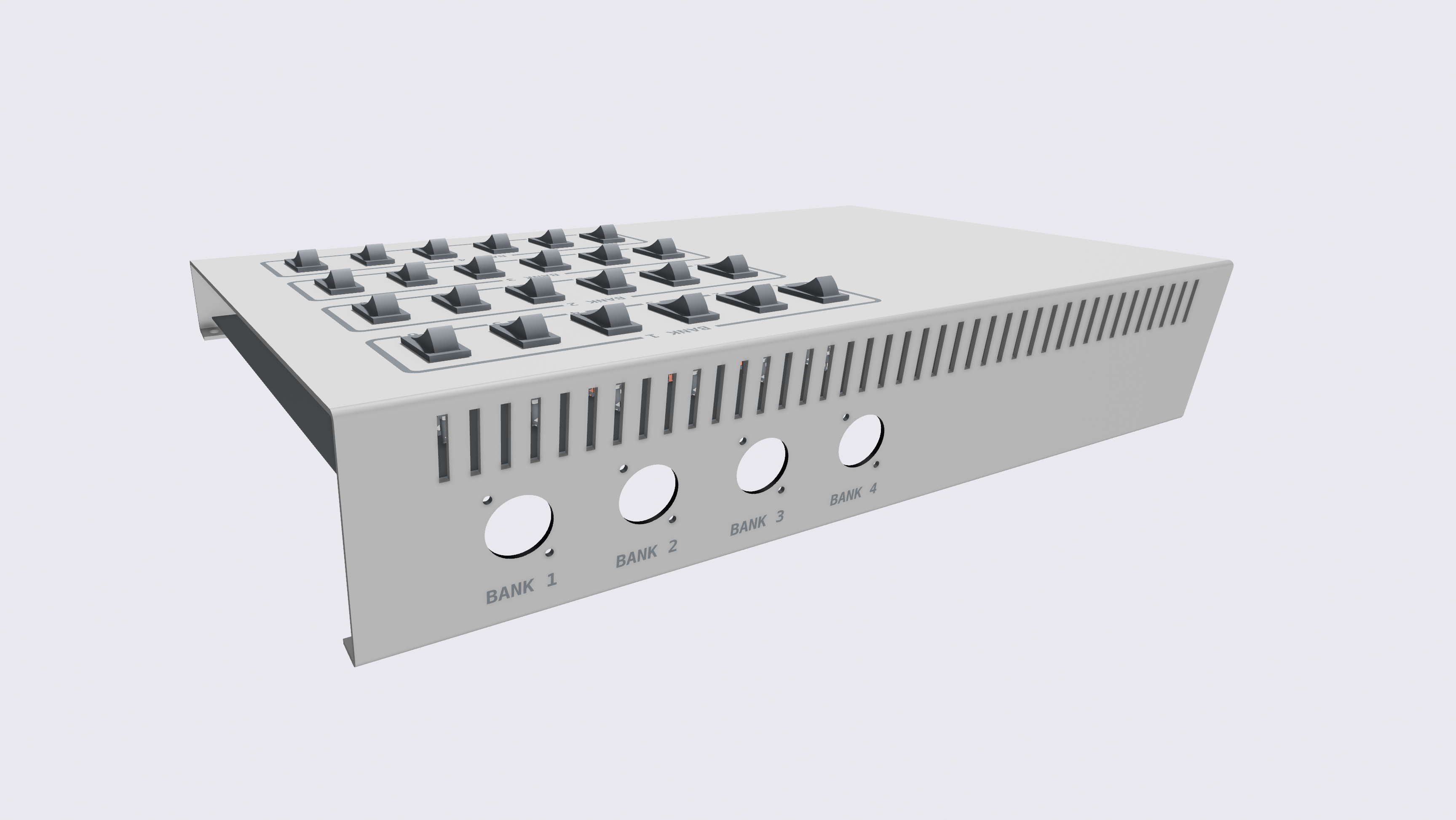
With the creation of the STEP files, I was able to start parts placement on the launch controller panel. I've produced a software virtualization of my efforts so far. The controller will have four (4) banks of six (6) pads. This will handle out existing two sawhorses based rod pads. The other two banks should suffice for all other needs. Everything will be color coded too. Each bank of switches will have an integral LED lamp which will serve for continuity testing. The color are red, blue, green and yellow. The cables to the pads will also be color coded with these colors.
As the pieces needed (and invariably lost in the absolute elsewhere of UPS, Fed(up)Ex, and USPS) arrive, I will add to the CAD defining the controller. When I have all of the panel populated with its components, I can create files for CNC cutting, DXF files for laser cutting and PCB layout.
If I recall correctly, I showed off a metal panel case that I purchased to make a new club launch controller at the November launch. I was hoping Mohave the project further along but the holidays and aftermath have cause many problems with getting parts delivered. Several purchased went missing ins shipping and I had to go through hell to get them resupplied. In fact, I was supposed to have eight (8) shipments today; only two arrived and the rest are listed dallied in shipping … again.
Today, I receive the switches to enable the pads. Sadly, they were accompanied with a link to only rudimentary engineering dimensional drawing; not CAD file (STEP). Now only that but after pulling out the calipers to confirm the drawings, I found they were wrong too. I spent a goodly amount of time today developing a model of the switches to produce STEP files that can drive the rest of the design.
I also received a large (18in × 12in) copper clad phenolic board that will become the PCB for the controller. All switches, connectors, logic, etc. will be handled by a PCB with headers to connect to some of the external physical interfaces. A quart of PCB etchant also arrived today.
With the creation of the STEP files, I was able to start parts placement on the launch controller panel. I've produced a software virtualization of my efforts so far. The controller will have four (4) banks of six (6) pads. This will handle out existing two sawhorses based rod pads. The other two banks should suffice for all other needs. Everything will be color coded too. Each bank of switches will have an integral LED lamp which will serve for continuity testing. The color are red, blue, green and yellow. The cables to the pads will also be color coded with these colors.
As the pieces needed (and invariably lost in the absolute elsewhere of UPS, Fed(up)Ex, and USPS) arrive, I will add to the CAD defining the controller. When I have all of the panel populated with its components, I can create files for CNC cutting, DXF files for laser cutting and PCB layout.
Quote from Eric Becher on February 3, 2024, 12:12 amWe'll have to paint the racks and launch pads colors to match the switch banks.
Or we can make little colored signs with numbers and stake them in front of each launch pad.
Or not.
We'll have to paint the racks and launch pads colors to match the switch banks.
Or we can make little colored signs with numbers and stake them in front of each launch pad.
Or not.
Quote from Admin on February 3, 2024, 7:04 amQuote from Eric Becher on February 3, 2024, 12:12 amWe'll have to paint the racks and launch pads colors to match the switch banks.
Or we can make little colored signs with numbers and stake them in front of each launch pad.
Or not.
When we held the 50th Anniversary of Apollo 11 Launch, I'd made large pad number signs — 1 through 6 in black and 1 through 6 in red for visibility. Also several for the standalone launchpads.
Quote from Eric Becher on February 3, 2024, 12:12 amWe'll have to paint the racks and launch pads colors to match the switch banks.
Or we can make little colored signs with numbers and stake them in front of each launch pad.
Or not.
When we held the 50th Anniversary of Apollo 11 Launch, I'd made large pad number signs — 1 through 6 in black and 1 through 6 in red for visibility. Also several for the standalone launchpads.
Quote from Admin on February 3, 2024, 7:22 amQuote from Ckirlew on February 2, 2024, 10:12 pmReally looking forward to this. I hope I can keep my colors straight.
That's mostly to keeps the cabling coordinated.
I really don't understand how people got through the Christmas season this year ordering on-line. I've had more shipments over the Christmas shopping season and thereafter go missing in transit. That has greatly impeded getting this thing done. Three of eight things I (re-)ordered that were to arrive yesterday actually arrived.
Sadly, no more Radio Shack (meh), Lafayette Electronics, or Atkinson and Smith to buy electronics things off the shelf. There is that Micro Center in Patterson which carries some hobby electronics but it too is woefully lacking in that department. It's a great source for computer gear and where I purchased my 3D printer. When I'm in its area, I drop in for 3D printer filament because they usually have a sale on much of it. So, the only way to get electronic components today seems to be on-line.
BTW, I have never had a piece of PCB copper-clad phenolic the size of that which arrived yesterday. I used to make my own PCBs for amplifiers and synthesizer modules from Radio-Electronics and Popular Electronics mags as well as Craig Anderton's books, and then for circuits I designed throughout college; however, those were typically small PCBs. This one will be a challenge. I'll need to make a larger etching tank.
Quote from Ckirlew on February 2, 2024, 10:12 pmReally looking forward to this. I hope I can keep my colors straight.
That's mostly to keeps the cabling coordinated.
I really don't understand how people got through the Christmas season this year ordering on-line. I've had more shipments over the Christmas shopping season and thereafter go missing in transit. That has greatly impeded getting this thing done. Three of eight things I (re-)ordered that were to arrive yesterday actually arrived.
Sadly, no more Radio Shack (meh), Lafayette Electronics, or Atkinson and Smith to buy electronics things off the shelf. There is that Micro Center in Patterson which carries some hobby electronics but it too is woefully lacking in that department. It's a great source for computer gear and where I purchased my 3D printer. When I'm in its area, I drop in for 3D printer filament because they usually have a sale on much of it. So, the only way to get electronic components today seems to be on-line.
BTW, I have never had a piece of PCB copper-clad phenolic the size of that which arrived yesterday. I used to make my own PCBs for amplifiers and synthesizer modules from Radio-Electronics and Popular Electronics mags as well as Craig Anderton's books, and then for circuits I designed throughout college; however, those were typically small PCBs. This one will be a challenge. I'll need to make a larger etching tank.
Quote from Ckirlew on February 3, 2024, 10:14 amI still have those signs or we can use the one I created below. It should help keep things organized.
Red
Blue
Green
Yellow
I still have those signs or we can use the one I created below. It should help keep things organized.
Red
Blue
Green
Yellow
Quote from Brian C. on February 3, 2024, 3:43 pmDoes that mean the pads are now going to be reumbered as RED ONE, GREEN ONE, BLUE ONE and so forth?
Or would that just be too confusing? Never mind.... I'm already confused.
Does that mean the pads are now going to be reumbered as RED ONE, GREEN ONE, BLUE ONE and so forth?
Or would that just be too confusing? Never mind.... I'm already confused.
Quote from Admin on February 7, 2024, 1:10 pmI received more of the components. After contacting the mgr.'s, none had STEP files, so I've been busy building the STEP files from manual measurements of them using my digital calipers. It's a slow process but it'll allow precise .DXF files to be produced to CNC and laser cutting. It'll also allow a 3D visualization of the controller before there is a single screw turned or hole made in any of the materials.
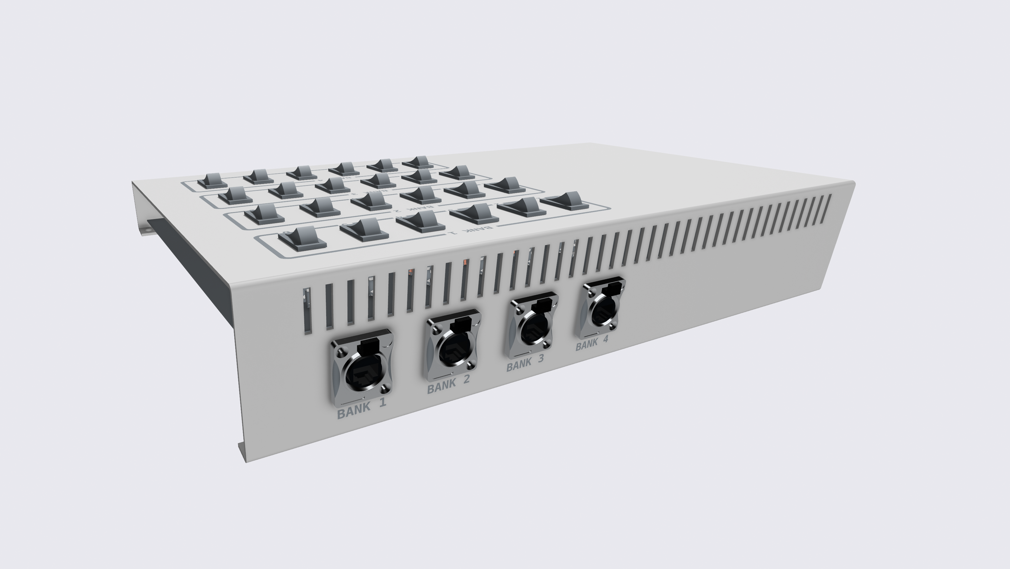
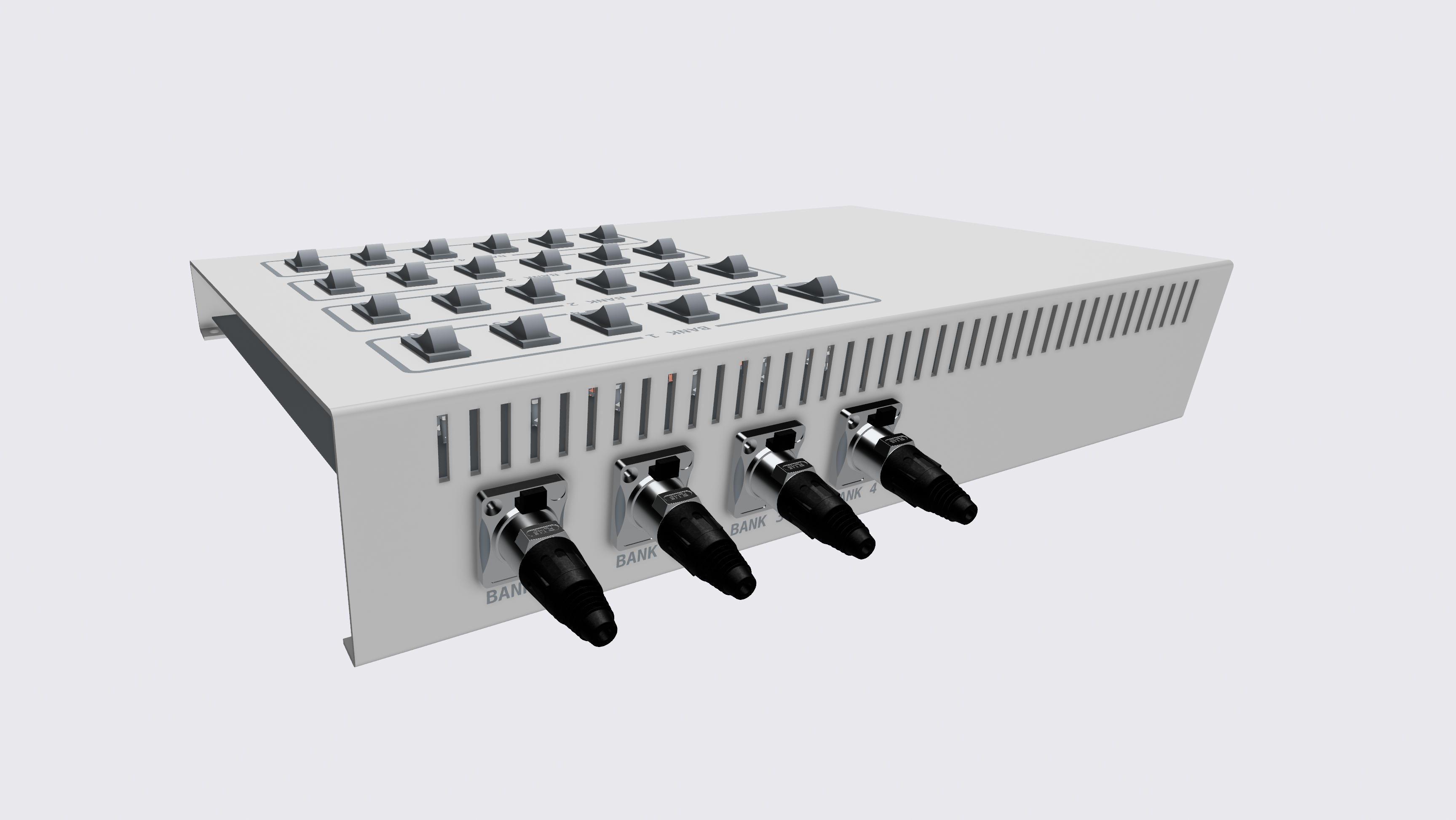
I believe it was Ken who was concerned about using CAT-5 because of the RJ45 connectors on the typical CAT-5 cable. I have purchased ruggedized CAT-5 connectors and jacks. These will hold up well with the typical abuses scene out at the field. I did NOT add the rubber weatherized covers for the jacks on the rear apron of the controller but I will, when completed, install them. Here are come visualizations of the rear apron with the connector for the four banks of cabling to the pads. The distribution boxes at the pads will also have the same ruggedized RJ45 connections.
I received more of the components. After contacting the mgr.'s, none had STEP files, so I've been busy building the STEP files from manual measurements of them using my digital calipers. It's a slow process but it'll allow precise .DXF files to be produced to CNC and laser cutting. It'll also allow a 3D visualization of the controller before there is a single screw turned or hole made in any of the materials.
I believe it was Ken who was concerned about using CAT-5 because of the RJ45 connectors on the typical CAT-5 cable. I have purchased ruggedized CAT-5 connectors and jacks. These will hold up well with the typical abuses scene out at the field. I did NOT add the rubber weatherized covers for the jacks on the rear apron of the controller but I will, when completed, install them. Here are come visualizations of the rear apron with the connector for the four banks of cabling to the pads. The distribution boxes at the pads will also have the same ruggedized RJ45 connections.
Uploaded files:Quote from Eric Becher on February 7, 2024, 1:25 pmLooks real nice and slick. Make sure there is plenty of room for a CENJARS sticker!
I don't know if you bought the "rubber weatherized covers for the jacks" already. My 1-cent opinion is that we don't need weather resistant connections since we hardly ever launch in rain, HOWEVER, if they are sturdier and will help resist an accidental tug or bump (perhaps why you specified them in the first place?) than I am all for it.
Add about 10 more banks and you can sell it to MDRA for $6,500!
When you can, send me some cost receipts, or whatever you have and I can apply for the NAR grant.
Looks real nice and slick. Make sure there is plenty of room for a CENJARS sticker!
I don't know if you bought the "rubber weatherized covers for the jacks" already. My 1-cent opinion is that we don't need weather resistant connections since we hardly ever launch in rain, HOWEVER, if they are sturdier and will help resist an accidental tug or bump (perhaps why you specified them in the first place?) than I am all for it.
Add about 10 more banks and you can sell it to MDRA for $6,500!
When you can, send me some cost receipts, or whatever you have and I can apply for the NAR grant.
Quote from Admin on February 7, 2024, 2:08 pmQuote from Eric Becher on February 7, 2024, 1:25 pmLooks real nice and slick. Make sure there is plenty of room for a CENJARS sticker!
There'll be plenty of room on the bottom.
I don't know if you bought the "rubber weatherized covers for the jacks" already. My 1-cent opinion is that we don't need weather resistant connections since we hardly ever launch in rain, HOWEVER, if they are sturdier and will help resist an accidental tug or bump (perhaps why you specified them in the first place?) than I am all for it.
The covers are for the jacks to keep crud out. The cables are easily replaced;) but let's try to keep the controller from needing repairs.
Add about 10 more banks and you can sell it to MDRA for $6,500!
Wilson F/X, have you looked at their offering? I'm sorry but for $6500, they could get somebody to silkscreen their faceplates. Their boxes are all labeled with stickers which peel and scratch with use. Also, the crux of their boxes come out of the home electrical wiring aisle of the local hardware stores.
When you can, send me some cost receipts, or whatever you have and I can apply for the NAR grant.
I have a folder with all of the receipts.
Quote from Eric Becher on February 7, 2024, 1:25 pmLooks real nice and slick. Make sure there is plenty of room for a CENJARS sticker!
There'll be plenty of room on the bottom.
I don't know if you bought the "rubber weatherized covers for the jacks" already. My 1-cent opinion is that we don't need weather resistant connections since we hardly ever launch in rain, HOWEVER, if they are sturdier and will help resist an accidental tug or bump (perhaps why you specified them in the first place?) than I am all for it.
The covers are for the jacks to keep crud out. The cables are easily replaced;) but let's try to keep the controller from needing repairs.
Add about 10 more banks and you can sell it to MDRA for $6,500!
Wilson F/X, have you looked at their offering? I'm sorry but for $6500, they could get somebody to silkscreen their faceplates. Their boxes are all labeled with stickers which peel and scratch with use. Also, the crux of their boxes come out of the home electrical wiring aisle of the local hardware stores.
When you can, send me some cost receipts, or whatever you have and I can apply for the NAR grant.
I have a folder with all of the receipts.


