
Composite Warehouse HV-ARCAS 4.5inch 75mm MMT
Quote from VAXman on March 7, 2023, 3:26 pmThis is a view of the aft end (the butthole) of the ARCAS. External fillets have been added to each fin and the retainer thrust plate assembly has been epoxied in place. There is more detail of the Maklin fin jig for those interested.
This photo marks the end of the rocket assembly. The next planned phase is to apply paint to the ARCAS.
This is a view of the aft end (the butthole) of the ARCAS. External fillets have been added to each fin and the retainer thrust plate assembly has been epoxied in place. There is more detail of the Maklin fin jig for those interested.
This photo marks the end of the rocket assembly. The next planned phase is to apply paint to the ARCAS.
Quote from VAXman on March 12, 2023, 11:44 amDue to the mass of this rocket, I opted to use six(6) nylon rivets to secure the upper payload airframe tube to the deployment av-bay. I opted to use four (4) shear pins (2-56 nylon) to secure the nosecone on this same tube; therefore, the six (6) nylon rivets provides significantly more connective strength than the shear pins insuring separation at the nosecone and not at the av-bay.
While at it, this is a little better detail of the PML (Public Missiles Ltd.) 1515 linear rail guide I've installed.
Due to the mass of this rocket, I opted to use six(6) nylon rivets to secure the upper payload airframe tube to the deployment av-bay. I opted to use four (4) shear pins (2-56 nylon) to secure the nosecone on this same tube; therefore, the six (6) nylon rivets provides significantly more connective strength than the shear pins insuring separation at the nosecone and not at the av-bay.
While at it, this is a little better detail of the PML (Public Missiles Ltd.) 1515 linear rail guide I've installed.
Quote from Eric Becher on March 12, 2023, 11:51 amI recommend Behr Premium Plus, available in nearly limitless colors, and a variety of finishes. Easy to clean and stands the test of time, even in a busy family household. Paint sample jars are available if you want to see how it looks in your space. Experts are always on hand to help you with your project so you get right. Available at your local Home Depot. (That's the messy orange store, not that nice blue one) 😂
I recommend Behr Premium Plus, available in nearly limitless colors, and a variety of finishes. Easy to clean and stands the test of time, even in a busy family household. Paint sample jars are available if you want to see how it looks in your space. Experts are always on hand to help you with your project so you get right. Available at your local Home Depot. (That's the messy orange store, not that nice blue one) 😂
Quote from VAXman on March 12, 2023, 12:13 pmEver since I did my L2 with a PML (Public Missiles Ltd.) 4 inch AIM-120 AMRAAM, I have employed a PML Intellicone style av-bay for tracking electronics. I currently have two (2) sizes:
- a 54mm for larger rockets permitting me to fly my Eggtimer Rocketry Eggfinder GPS transmitter with a 7.5dBi antenna,
- a 38mm for narrow rockets equipped with an Eggtimer Rocketry Eggfinder mini GPS transmitter.
This is a photo of the PML 54mm Intellicone sled with the Eggtimer Rocketry Eggfinder GPS transmitter and antenna. It mounts inside a length of 54mm tubing. I opted for fiberglass in this build to keep everything fiberglass. The sled mounts into the tube and it is secured with two set-screws that turn out into corresponding holes at the end of the tube.
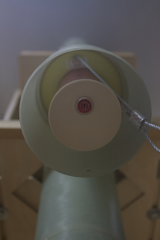
The 54mm tube is epoxied into the nosecone and a centering ring (CR). The CR sits atop of the shoulder of the nosecone's coupler. A one (1) foot of 3/32-inch weldless galvanized steel cable is used to make an attachment point for the nosecone using 3/32-inch ferrule for the loop and a 3/32-inch stop on the end of the cable. The ferrule and stop have a small amount of JB weld applied to their interior and then, both were significantly compressed in my bench vise to secure them. This attachment scheme is the same as the PML Intellicone's scheme if one purchased one from PML; however, I use slightly stronger/thicker steel cable. The ferrule was then covered with heat shrink tubing to insure that none of the recovery laundry could be snagged and torn by the end of the steel cable. This photo shows this av-bay detail.
This is a photo with the tracking sled inserted into the nosecone av-bay. To simplify enabling the electronics, I've added a key switch to the end of the av-bay sled. I chose a key switch because it's the type of switch that can not accidentally be enabled in transit which would discharge the 2S 1000mAh LiPo battery powering the transmitter.
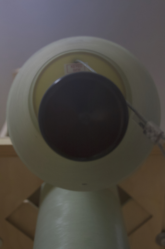
The end of the av-bay, once the sled has been installed, is covered by a tight fitting rubber cap to keep the ejection charge detritus out of the key switch.
Ever since I did my L2 with a PML (Public Missiles Ltd.) 4 inch AIM-120 AMRAAM, I have employed a PML Intellicone style av-bay for tracking electronics. I currently have two (2) sizes:
- a 54mm for larger rockets permitting me to fly my Eggtimer Rocketry Eggfinder GPS transmitter with a 7.5dBi antenna,
- a 38mm for narrow rockets equipped with an Eggtimer Rocketry Eggfinder mini GPS transmitter.
This is a photo of the PML 54mm Intellicone sled with the Eggtimer Rocketry Eggfinder GPS transmitter and antenna. It mounts inside a length of 54mm tubing. I opted for fiberglass in this build to keep everything fiberglass. The sled mounts into the tube and it is secured with two set-screws that turn out into corresponding holes at the end of the tube.
![]()
The 54mm tube is epoxied into the nosecone and a centering ring (CR). The CR sits atop of the shoulder of the nosecone's coupler. A one (1) foot of 3/32-inch weldless galvanized steel cable is used to make an attachment point for the nosecone using 3/32-inch ferrule for the loop and a 3/32-inch stop on the end of the cable. The ferrule and stop have a small amount of JB weld applied to their interior and then, both were significantly compressed in my bench vise to secure them. This attachment scheme is the same as the PML Intellicone's scheme if one purchased one from PML; however, I use slightly stronger/thicker steel cable. The ferrule was then covered with heat shrink tubing to insure that none of the recovery laundry could be snagged and torn by the end of the steel cable. This photo shows this av-bay detail.
This is a photo with the tracking sled inserted into the nosecone av-bay. To simplify enabling the electronics, I've added a key switch to the end of the av-bay sled. I chose a key switch because it's the type of switch that can not accidentally be enabled in transit which would discharge the 2S 1000mAh LiPo battery powering the transmitter.
The end of the av-bay, once the sled has been installed, is covered by a tight fitting rubber cap to keep the ejection charge detritus out of the key switch.
Quote from VAXman on March 12, 2023, 1:55 pmI'm publishing this here for all who have never seen or used a Marsa Systems MARSA33LHD altimeter. The MARSA33 is a very nice and very capable altimeter. It's overkill for application in my Composite Warehouse HV-ARCAS but it's also extremely reliable, so I'm using two of them in the ARCAS av-bay.
The following video shows one of the Marsa Systems MARSA33LHD altimeter on one of my rocket avionics bay sleds. The MARSA's parasitic display board is attached in this video to show the diagnostics available. In this video, I demonstrate the MARSA's output diagnostics for electric match continuity and pyro testing. In lieu of electric matches, I have employed small incandescent "Christmas" tree bulbs with leads that are the same span as the JST SM-2 connectors.
https://www.youtube.com/watch?v=mwSB1io5CyE&t=11s
This is a video of a Marsa Systems MARSA33LHD altimeter on one of my rocket avionics bay sleds. The MARSA's parasitic display board is attached in this video to show the diagnostics available. In this video, I demonstrate the MARSA's simulation mode which can be used to test deployment system. The MARSA goes thought a simulated flight. The self-test diagnostics are run and then, the MARSA simulates a flight to approximately 3000 feet (this value changes from test to test). When the simulated flight attains apogee, the lamp on the left can be seen indicating firing the drogue deployment charge. The MARSA then simulates falling from apogee to the pre-ordained altitude (700 feet) for firing of the main parachute deployment charge. This is shown with the lamp on the right. When the simulation is complete, the MARSA proceeds to "beep" out the altitude.
https://www.youtube.com/watch?v=Nrx6klRY3bU
This is a video of a Marsa Systems MARSA33LHD altimeter on one of my rocket avionics bay sleds. The MARSA's parasitic display board has been removed for this video to imitate actual flight condition. In this video, I demonstrate the MARSA's simulation mode which can be used to test deployment system. The MARSA goes thought a simulated flight. The simulation mode is enabled by holding the on-board joystick to the left and then, powering the MARSA. Once placed in simulation mode, the MARSA can be powered down. If doing an actual ground test, the MARSA and av-bay sled would be installed in a rocket with electrical matches, FFFFg black powder and the recovery parachutes. When powered on again, the MARSA is still in simulation mode. The self-test diagnostics are run and then, the MARSA simulates a flight to approximately 3000 feet (this value changes from test to test). When the simulated flight attains apogee, the lamp on the left can be seen indicating firing the drogue deployment charge. The MARSA then simulates falling from apogee to the pre-ordained altitude (700 feet) for firing of the main parachute deployment charge. This is shown with the lamp on the right. When the simulation is complete, the MARSA proceeds to "beep" out the altitude.
https://www.youtube.com/watch?v=v7dPRiLlqO0
I'm publishing this here for all who have never seen or used a Marsa Systems MARSA33LHD altimeter. The MARSA33 is a very nice and very capable altimeter. It's overkill for application in my Composite Warehouse HV-ARCAS but it's also extremely reliable, so I'm using two of them in the ARCAS av-bay.
The following video shows one of the Marsa Systems MARSA33LHD altimeter on one of my rocket avionics bay sleds. The MARSA's parasitic display board is attached in this video to show the diagnostics available. In this video, I demonstrate the MARSA's output diagnostics for electric match continuity and pyro testing. In lieu of electric matches, I have employed small incandescent "Christmas" tree bulbs with leads that are the same span as the JST SM-2 connectors.
This is a video of a Marsa Systems MARSA33LHD altimeter on one of my rocket avionics bay sleds. The MARSA's parasitic display board is attached in this video to show the diagnostics available. In this video, I demonstrate the MARSA's simulation mode which can be used to test deployment system. The MARSA goes thought a simulated flight. The self-test diagnostics are run and then, the MARSA simulates a flight to approximately 3000 feet (this value changes from test to test). When the simulated flight attains apogee, the lamp on the left can be seen indicating firing the drogue deployment charge. The MARSA then simulates falling from apogee to the pre-ordained altitude (700 feet) for firing of the main parachute deployment charge. This is shown with the lamp on the right. When the simulation is complete, the MARSA proceeds to "beep" out the altitude.
This is a video of a Marsa Systems MARSA33LHD altimeter on one of my rocket avionics bay sleds. The MARSA's parasitic display board has been removed for this video to imitate actual flight condition. In this video, I demonstrate the MARSA's simulation mode which can be used to test deployment system. The MARSA goes thought a simulated flight. The simulation mode is enabled by holding the on-board joystick to the left and then, powering the MARSA. Once placed in simulation mode, the MARSA can be powered down. If doing an actual ground test, the MARSA and av-bay sled would be installed in a rocket with electrical matches, FFFFg black powder and the recovery parachutes. When powered on again, the MARSA is still in simulation mode. The self-test diagnostics are run and then, the MARSA simulates a flight to approximately 3000 feet (this value changes from test to test). When the simulated flight attains apogee, the lamp on the left can be seen indicating firing the drogue deployment charge. The MARSA then simulates falling from apogee to the pre-ordained altitude (700 feet) for firing of the main parachute deployment charge. This is shown with the lamp on the right. When the simulation is complete, the MARSA proceeds to "beep" out the altitude.
Quote from VAXman on March 12, 2023, 5:17 pmQuote from Eric Becher on March 12, 2023, 11:51 amI recommend Behr Premium Plus, available in nearly limitless colors, and a variety of finishes. Easy to clean and stands the test of time, even in a busy family household. Paint sample jars are available if you want to see how it looks in your space. Experts are always on hand to help you with your project so you get right. Available at your local Home Depot. (That's the messy orange store, not that nice blue one)
Huh? Where did paint come into this?
Why would anyone want to paint a rocket with latex house paint? And, it wouldn't adhere to the composites.

Quote from Eric Becher on March 12, 2023, 11:51 amI recommend Behr Premium Plus, available in nearly limitless colors, and a variety of finishes. Easy to clean and stands the test of time, even in a busy family household. Paint sample jars are available if you want to see how it looks in your space. Experts are always on hand to help you with your project so you get right. Available at your local Home Depot. (That's the messy orange store, not that nice blue one)
Huh? Where did paint come into this?
Why would anyone want to paint a rocket with latex house paint? And, it wouldn't adhere to the composites.
Quote from Eric Becher on March 12, 2023, 7:18 pmYou did: "The next planned phase is to apply paint to the ARCAS."
So I offered a (perhaps not so) helpful suggestion.
😁
You did: "The next planned phase is to apply paint to the ARCAS."
So I offered a (perhaps not so) helpful suggestion.
😁
Quote from VAXman on March 12, 2023, 8:07 pmI don't see Mother Nature being too congenial. A few weeks ago, 60ºF+ and now they're talking snow. Grrr. If I do fly the ARCAS, it may be naked — not me, the rocket.
I don't see Mother Nature being too congenial. A few weeks ago, 60ºF+ and now they're talking snow. Grrr. If I do fly the ARCAS, it may be naked — not me, the rocket.
Quote from VAXman on March 17, 2023, 6:22 amGround testing complete!
Using the ejection charge calculator at https://rocketrycalculator.com/, it calculated the following ejection charge amounts as:
- Main: 1.3g FFFFg for a 4.5inch diameter airframe of 20 inch length using four #2-56 nylon shear pins
- Drogue: 1.8g FFFFg for a 4.5inch diameter airframe of 28 inch length using four #2-56 nylon shear pins
I rounded these values up to 1.5g (15% more then 1.3g) and 2.0g (11% more than 1.8g).
Thankfully, yesterday was a relatively nice day to ground test with these calculated black powder charges. I setup my usual 8ft folding table which was stored under the pergola. I then walked into the garage to get some paper towels to wipe the table clean when I spied the Dewalt mitre saw stand and thought, "Why not?" It's certainly strong; it can support the mitre saw which alone weighs in at 56lbs not to mention the materials that may be cut. So, I lugged it out and unfolded its legs.
I then readied the rocket for the ground test. The rocket was secured to the saw stand, which I padded with a folded moving blanked, with some straps. The "business end" of the rocket was abutted up to one of my fence posts to arrest any recoil from the ejection tests.
The following video shows the result of the main parachute deployment. The nosecone and laundry were successfully deployed. The parachute was not released from the deployment bag due to the nosecone not traveling far enough in the test. The kevlar harness is 30ft in length and gravity had the nosecone on the ground at about 15ft.
https://www.youtube.com/watch?v=fAPWPgJ4Dgk
The video below shows the result of the drogue parachute deployment. The nosecone, upper airframe, avionics bay and laundry were successfully deployed. The parachute, a BAMA 2ft balute, was released from the deployment bag due to its smaller size even through the entire forward assembly did not travel far. The kevlar harness is 30ft in length plus 8ft of kevlar mounting/attachment strap affixed to the MMT. Also, to perform this test, the rocket needed a motor. I assembled my 75mm 4 grain CTI casing with a filler to mimic a fully loaded motor. This completed air-tight enclosure of the booster section for testing.
https://www.youtube.com/watch?v=V2qj4SUNiqc
By the way, as the day progressed, it became so nice that I was able to perform the last test in just a T-shirt.
Ground testing complete!
Using the ejection charge calculator at https://rocketrycalculator.com/, it calculated the following ejection charge amounts as:
- Main: 1.3g FFFFg for a 4.5inch diameter airframe of 20 inch length using four #2-56 nylon shear pins
- Drogue: 1.8g FFFFg for a 4.5inch diameter airframe of 28 inch length using four #2-56 nylon shear pins
I rounded these values up to 1.5g (15% more then 1.3g) and 2.0g (11% more than 1.8g).
Thankfully, yesterday was a relatively nice day to ground test with these calculated black powder charges. I setup my usual 8ft folding table which was stored under the pergola. I then walked into the garage to get some paper towels to wipe the table clean when I spied the Dewalt mitre saw stand and thought, "Why not?" It's certainly strong; it can support the mitre saw which alone weighs in at 56lbs not to mention the materials that may be cut. So, I lugged it out and unfolded its legs.
I then readied the rocket for the ground test. The rocket was secured to the saw stand, which I padded with a folded moving blanked, with some straps. The "business end" of the rocket was abutted up to one of my fence posts to arrest any recoil from the ejection tests.
The following video shows the result of the main parachute deployment. The nosecone and laundry were successfully deployed. The parachute was not released from the deployment bag due to the nosecone not traveling far enough in the test. The kevlar harness is 30ft in length and gravity had the nosecone on the ground at about 15ft.
The video below shows the result of the drogue parachute deployment. The nosecone, upper airframe, avionics bay and laundry were successfully deployed. The parachute, a BAMA 2ft balute, was released from the deployment bag due to its smaller size even through the entire forward assembly did not travel far. The kevlar harness is 30ft in length plus 8ft of kevlar mounting/attachment strap affixed to the MMT. Also, to perform this test, the rocket needed a motor. I assembled my 75mm 4 grain CTI casing with a filler to mimic a fully loaded motor. This completed air-tight enclosure of the booster section for testing.
By the way, as the day progressed, it became so nice that I was able to perform the last test in just a T-shirt.
Quote from Brian C. on March 19, 2023, 9:18 pmSo many questions, so little day left.... I've seen these ejection charge tests done by Whats-his-name who does Rocket Vlogs on youtube, but I'm not sure what the procedure is. How are you tricking the altimeter to believe it's time to pop the chute? Or are you igniting the black powder manually, and if so, via what method? I don't see dangling wires in the video, so, is there some kind of remote control you've invested in? Or is a manual control method a different "program" built into the altimeter that you're able to run that gives you 3 minutes to get out of the way before it fires? Like those timers built into cameras that take a photo after a pre-determined countdown? I have yet to do any electronics in a rocket, so naturally, I am clueless.
So many questions, so little day left.... I've seen these ejection charge tests done by Whats-his-name who does Rocket Vlogs on youtube, but I'm not sure what the procedure is. How are you tricking the altimeter to believe it's time to pop the chute? Or are you igniting the black powder manually, and if so, via what method? I don't see dangling wires in the video, so, is there some kind of remote control you've invested in? Or is a manual control method a different "program" built into the altimeter that you're able to run that gives you 3 minutes to get out of the way before it fires? Like those timers built into cameras that take a photo after a pre-determined countdown? I have yet to do any electronics in a rocket, so naturally, I am clueless.