
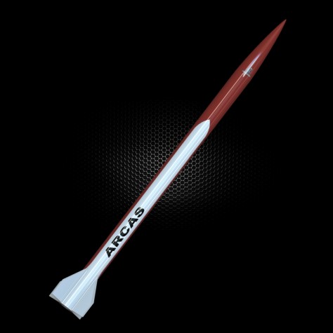
Composite Warehouse HV-ARCAS 4.5inch 75mm MMT
Quote from VAXman on January 29, 2023, 2:41 pmIn 2021, I purchased a Composite Warehouse HV-ARCAS kit. It's been sitting about for over a year and I decided I'd begin its assembly early this January. This rocket is 8+ft tall and has an airframe diameter of 4.5 inch (115mm) and 75mm motor mount. I'm going to devote this thread to detailing my work and progress on this rocket. Each entry I make will detail one assembled aspect of the rocket's build.
In 2021, I purchased a Composite Warehouse HV-ARCAS kit. It's been sitting about for over a year and I decided I'd begin its assembly early this January. This rocket is 8+ft tall and has an airframe diameter of 4.5 inch (115mm) and 75mm motor mount. I'm going to devote this thread to detailing my work and progress on this rocket. Each entry I make will detail one assembled aspect of the rocket's build.
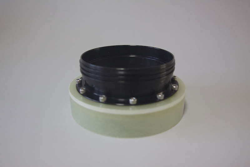
Quote from VAXman on January 29, 2023, 2:53 pmMOTOR RETAINER AND THRUST PLATE
To insure proper placement of the retainer on the thrust plate, I opened up Shapr3D (my 3D design software on my MacBook Pro) and designed a mock-up of the end of my 75mm Cesaroni motor case.
With the above printed, I assembled the male part of the Aeropak retainer, the thrust plate and the drilling guide together. I then used my milling machine to drill #31 holes in the thrust plate to accept the screws. The thrust plate is fiberglass, so I always select a slightly smaller hole size. I went with a #32 drill. After all of the screw holes were drilled, I taped them with a #6-32 tap. The flange was then affixed to the thrust plate with #6-32 stainless steel socket head cap screws.
MOTOR RETAINER AND THRUST PLATE
To insure proper placement of the retainer on the thrust plate, I opened up Shapr3D (my 3D design software on my MacBook Pro) and designed a mock-up of the end of my 75mm Cesaroni motor case.
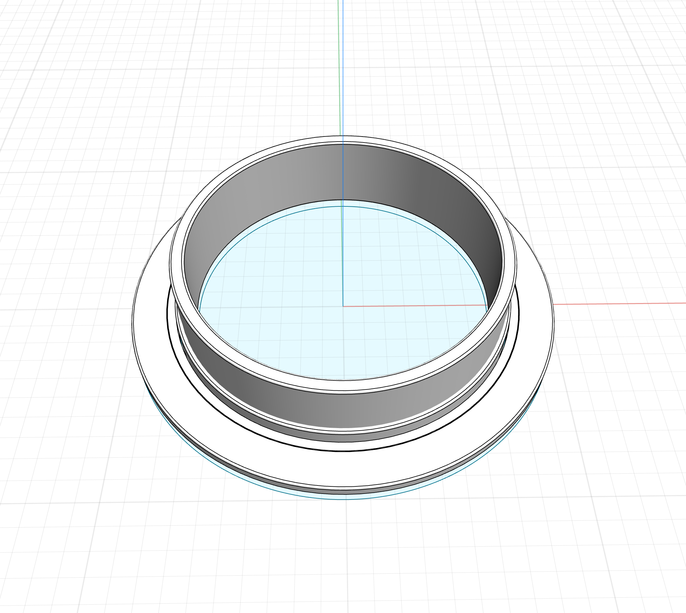
With the above printed, I assembled the male part of the Aeropak retainer, the thrust plate and the drilling guide together. I then used my milling machine to drill #31 holes in the thrust plate to accept the screws. The thrust plate is fiberglass, so I always select a slightly smaller hole size. I went with a #32 drill. After all of the screw holes were drilled, I taped them with a #6-32 tap. The flange was then affixed to the thrust plate with #6-32 stainless steel socket head cap screws.
Quote from VAXman on January 29, 2023, 3:23 pmAVIONICS BAY ELECTRONICS SLED
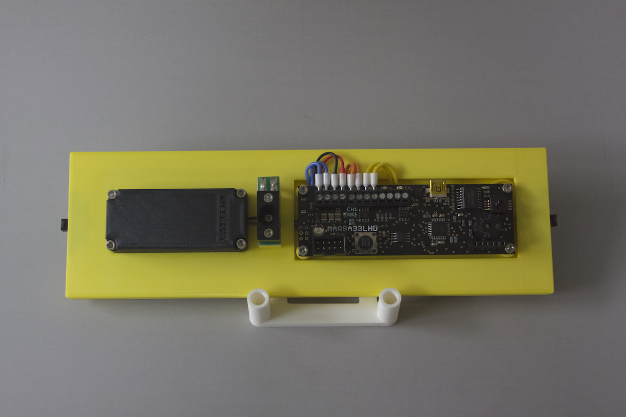
The next thing I took up to build is this rocket's avionics bay. Because of its size, this rocket will fly with two altimeters. I would have liked to use two disparate altimeters but my favorite altimeter, the PerfectFlite StratoLogger CF has been unavailable for well over a year now. Because of this fact, I opted to built the avionics bay with two Marsa Systems MARSA33LHD altimeters. They are rather expensive altimeters but they are worth every penny. I currently possess two. Because of their price, I decided to design an avionics bay sled that could be easily removed from one rocket and installed into another. This meant that I'd need a good quality quick disconnect system to disengage the sled from the avionics bay's bulkheads.
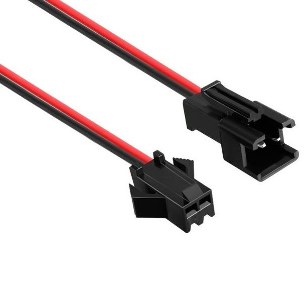
After a search for suitable connectors, I settled on JST SM-2 connectors. These connectors have a locking system which seemed ideal for this application. These connectors are shown in the following image.
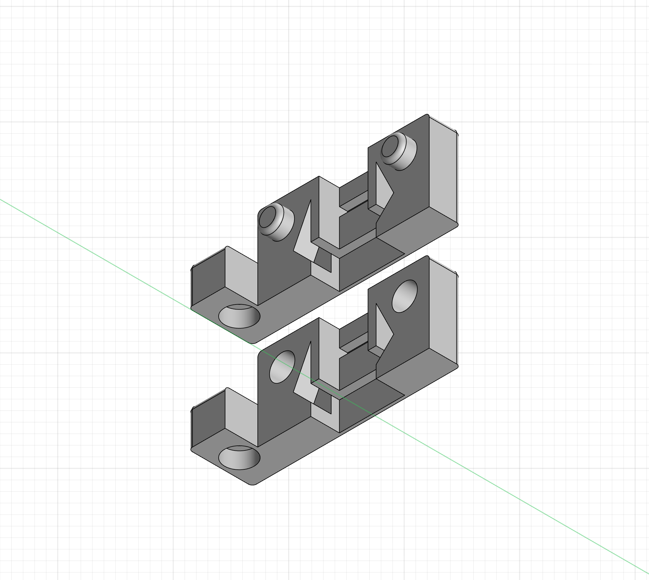
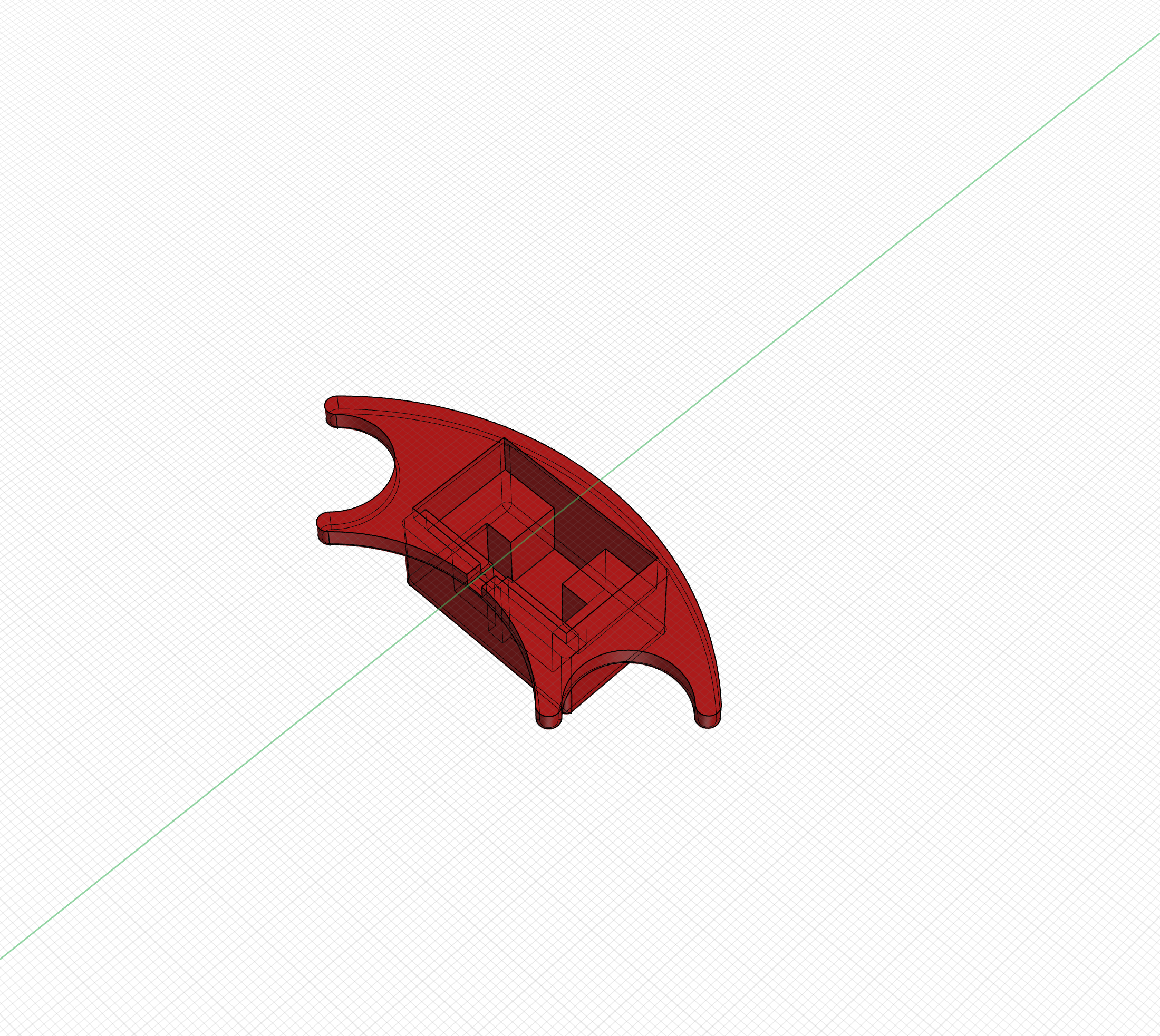
The female piece of this connector pair needed to be mounted in the ends of the avionics bay sleds. To accommodate them, I designed and 3D printed a panel mount clip scheme. The female connector is placed into this clip and then, the clip itself will be mounted into the ends of the sled. The following image shows the details of the clip I designed.
The sled was 3D designed and printed as well. Normally, I make my avionics sleds from acrylic (eg. plexiglass) cutting them using my router table and or milling machine; however, now that I possess a 3D printer, I can design more elaborate constructions and 3D print them as I sleep which I usually do as 3D printing can take many hours depending on the size of the print.
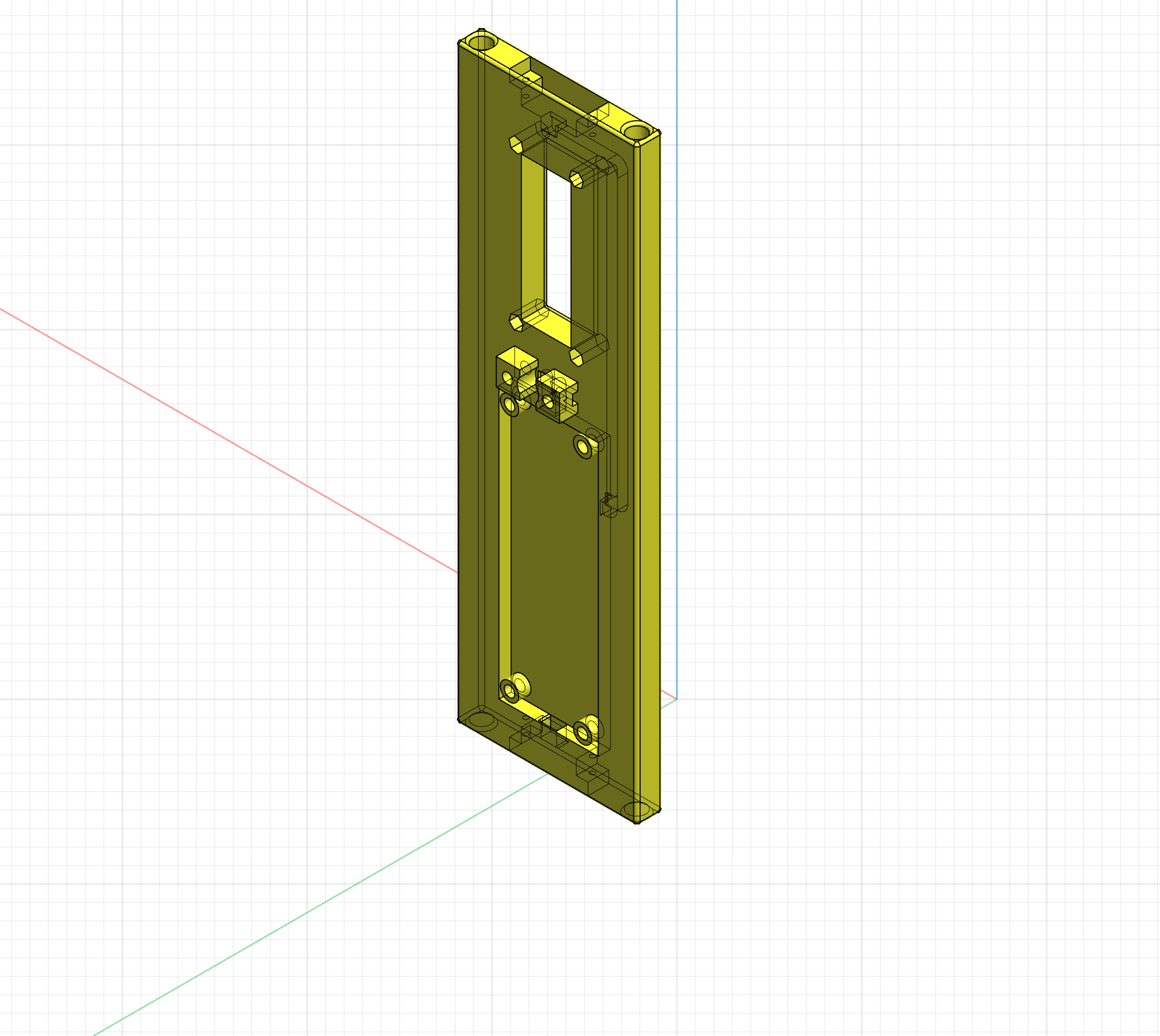
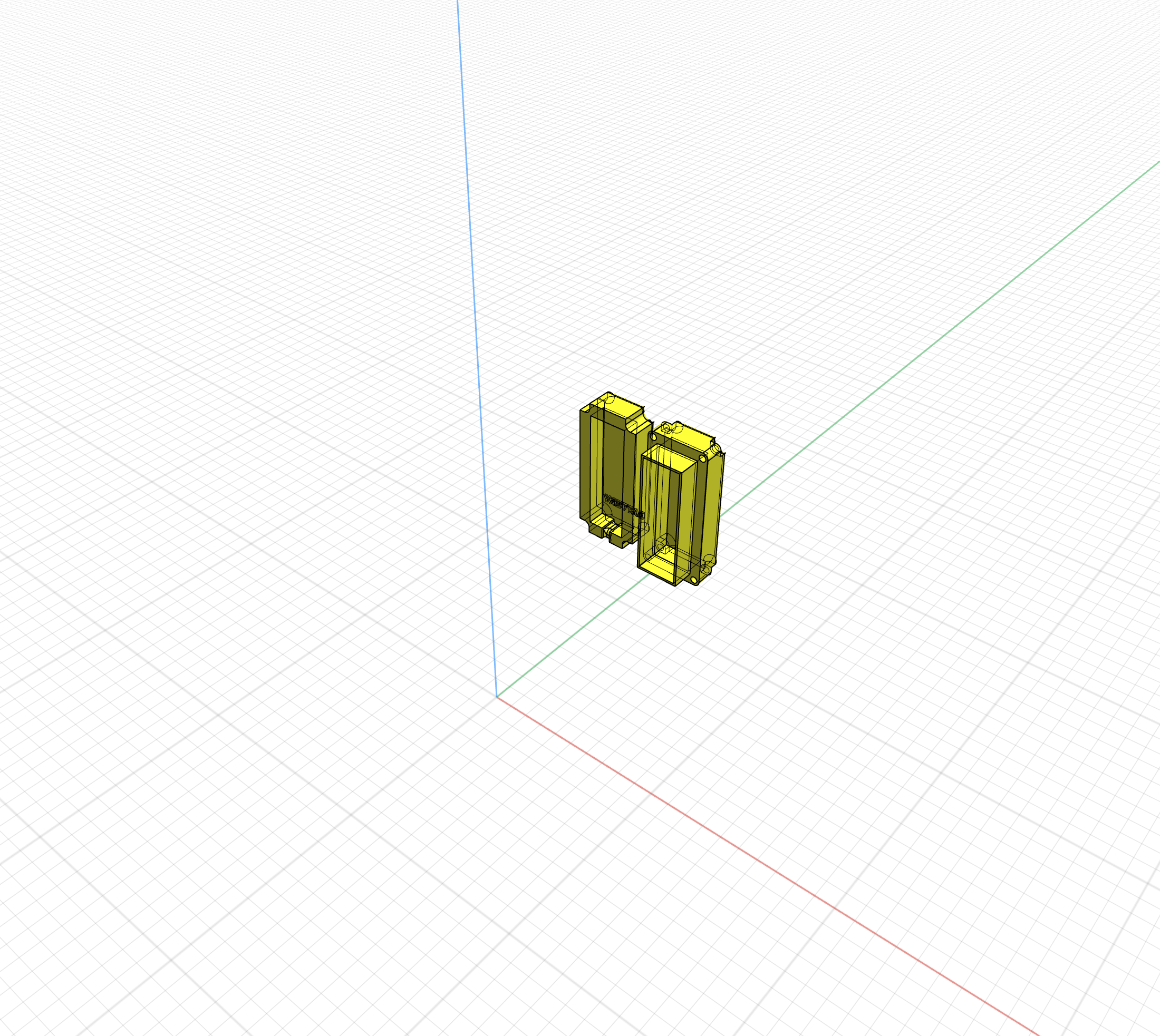
The design of the avionics sled employs accesses for the panel mount clips which hold the JST SM-2 connectors, a recessed well for the Marsa Systems MARSA33LHD altimeters, an elevated mounting platform for the screw switch, and an area for the battery. In addition, I wanted the wiring to be as concealed as possible for two reasons.
- To protect the wiring from damage and,
- To keep the resulting sled as neat as possible.
To accomplish this, there are cabling tunnels in the body of the sled. Wires are pulled through these tunnels and the cables are only exposed enough to be connected to the altimeter. The battery cover for the sled is two pieces with an opening in the middle of the sled just large enough to accommodate a 9 volt battery and its connector clip. The following images show the 3D design files for these sled components.
The JST SM-2 female is set into one half of the clip designed to hold it and the corresponding other half snaps over it securely holding the JST SM-2 in place. The connecting wires for the connectors are fed through the sled's tunnels. The JST SM-2 panel clips are then inserted into the ends of the sled and retained with two each #2-56×5/16inch stainless steel socket head cap screws.
The battery holder's screws are #4-40×1/2 inch stainless steel socket head cap screws that turn into a #4-40 hexagonal standoff pressed into the sled at each corner of the battery compartment. This mounting scheme offers the most secure retention of the battery in both lateral and longitudinal directions. The hexagonal standoffs relieve stresses on the sled, and they are stronger and more secure than melt in threaded ferrules.
AVIONICS BAY ELECTRONICS SLED
The next thing I took up to build is this rocket's avionics bay. Because of its size, this rocket will fly with two altimeters. I would have liked to use two disparate altimeters but my favorite altimeter, the PerfectFlite StratoLogger CF has been unavailable for well over a year now. Because of this fact, I opted to built the avionics bay with two Marsa Systems MARSA33LHD altimeters. They are rather expensive altimeters but they are worth every penny. I currently possess two. Because of their price, I decided to design an avionics bay sled that could be easily removed from one rocket and installed into another. This meant that I'd need a good quality quick disconnect system to disengage the sled from the avionics bay's bulkheads.
After a search for suitable connectors, I settled on JST SM-2 connectors. These connectors have a locking system which seemed ideal for this application. These connectors are shown in the following image.
The female piece of this connector pair needed to be mounted in the ends of the avionics bay sleds. To accommodate them, I designed and 3D printed a panel mount clip scheme. The female connector is placed into this clip and then, the clip itself will be mounted into the ends of the sled. The following image shows the details of the clip I designed.
The sled was 3D designed and printed as well. Normally, I make my avionics sleds from acrylic (eg. plexiglass) cutting them using my router table and or milling machine; however, now that I possess a 3D printer, I can design more elaborate constructions and 3D print them as I sleep which I usually do as 3D printing can take many hours depending on the size of the print.
The design of the avionics sled employs accesses for the panel mount clips which hold the JST SM-2 connectors, a recessed well for the Marsa Systems MARSA33LHD altimeters, an elevated mounting platform for the screw switch, and an area for the battery. In addition, I wanted the wiring to be as concealed as possible for two reasons.
- To protect the wiring from damage and,
- To keep the resulting sled as neat as possible.
To accomplish this, there are cabling tunnels in the body of the sled. Wires are pulled through these tunnels and the cables are only exposed enough to be connected to the altimeter. The battery cover for the sled is two pieces with an opening in the middle of the sled just large enough to accommodate a 9 volt battery and its connector clip. The following images show the 3D design files for these sled components.
The JST SM-2 female is set into one half of the clip designed to hold it and the corresponding other half snaps over it securely holding the JST SM-2 in place. The connecting wires for the connectors are fed through the sled's tunnels. The JST SM-2 panel clips are then inserted into the ends of the sled and retained with two each #2-56×5/16inch stainless steel socket head cap screws.
The battery holder's screws are #4-40×1/2 inch stainless steel socket head cap screws that turn into a #4-40 hexagonal standoff pressed into the sled at each corner of the battery compartment. This mounting scheme offers the most secure retention of the battery in both lateral and longitudinal directions. The hexagonal standoffs relieve stresses on the sled, and they are stronger and more secure than melt in threaded ferrules.
Quote from VAXman on January 29, 2023, 4:16 pmAVIONICS BAY BULKHEADS
With the avionics bay sled design and assembly complete, the next task to tackle was the physical avionics bay and its bulk heads.
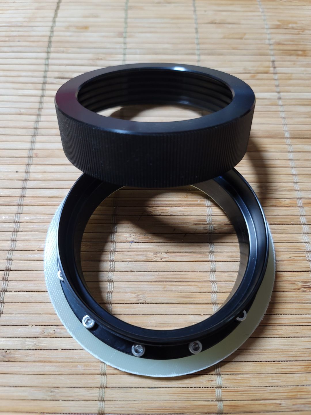
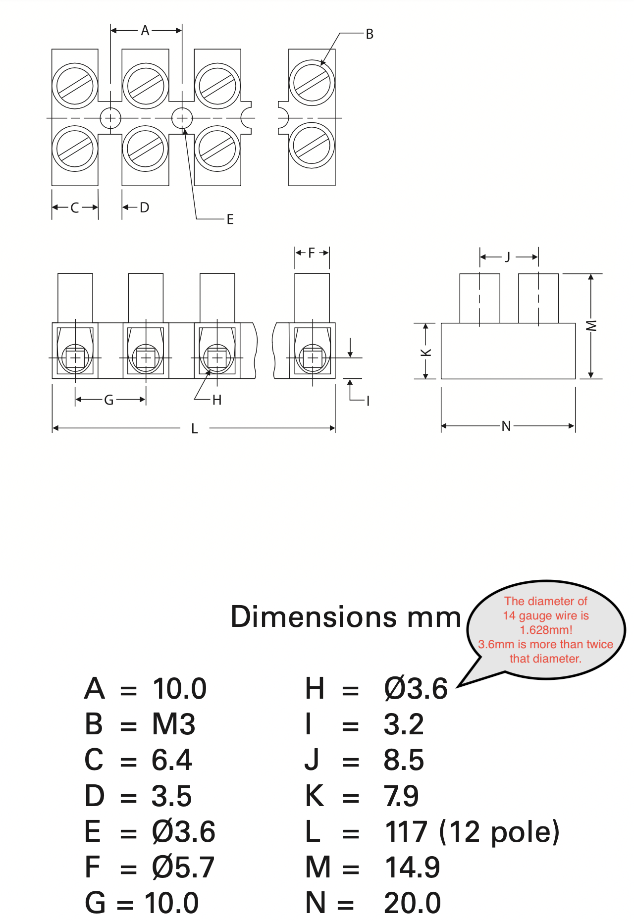
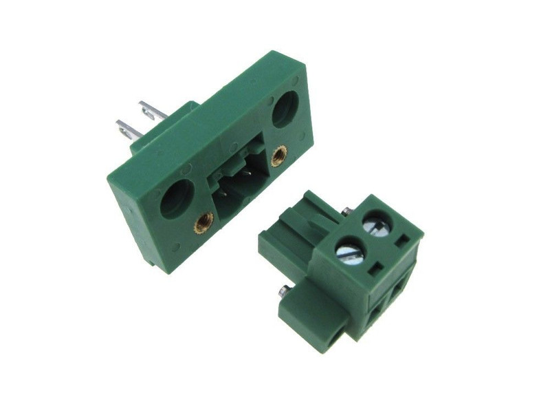
For several years now, I have employed a proper screw terminal connector in my avionics bays, not something intended for use by house-wiring jockeys inside breaker panels. The screw terminals I use allow a through the bulkhead connection for connecting the electric matches. Properly mounted, they are air tight and they're meant for/designed for use with 20-24 gauge wire, not 14-16 gauge Romex wire. I buy my electronics components from electronics supply houses, not Home Depot. 😉 These screw connectors are also two pieces. The actual piece which houses the screw terminals plugs into a second piece that is the through the panel socket. The following image details these connectors.
For the HV-ARCAS, I settled on a redundant altimeter scheme — primary and backup. Thus, to simplify this redundancy, there are two completely independent dual-deployment systems. To accommodate two completely independent systems, I decided to employ two sets of threaded rod to tie the avionics bulkheads together. This simplifies the sled design and it offers superior strength to the avionics bay.
Once again, I employed the 3D design software on my MacBook Pro and my 3D printer. I designed the avionics bay and then, used its dimensional figures to create a 3D printed drilling guide that I used with my milling machine to create the actual fiberglass bulkheads. This simplified my efforts on the milling machine. In the past I would need precision measurement to position the quill over the material. This also meant that I needed to spend significant time tramming and squaring up the fiberglass bulkheads before performing any mill cutting. With the 3D printed guide, I could lower the quill and cutter into the cutting guide and then, secure the workpiece to the traverse table. For the square holes needed for the through the wall screw terminal connector, I placed a collar around part of the cutter and then moved the traverse table to follow the square in the drilling guide. The smallest diameter mill cutter I have is 1/8 inch, so the corners would be rounded with a radius of 1/16 inch. No problem there because I have a good set of diamond files making it a quick, simple and fast task to square the corners. Note: If you are working on/with fiberglass and you do not have a set of diamond files, you're making much work for yourself. HarborFreight has a 10-file set for $7! So cheap that you can afford a backup set or sets. HarborFreight Diamond File Set
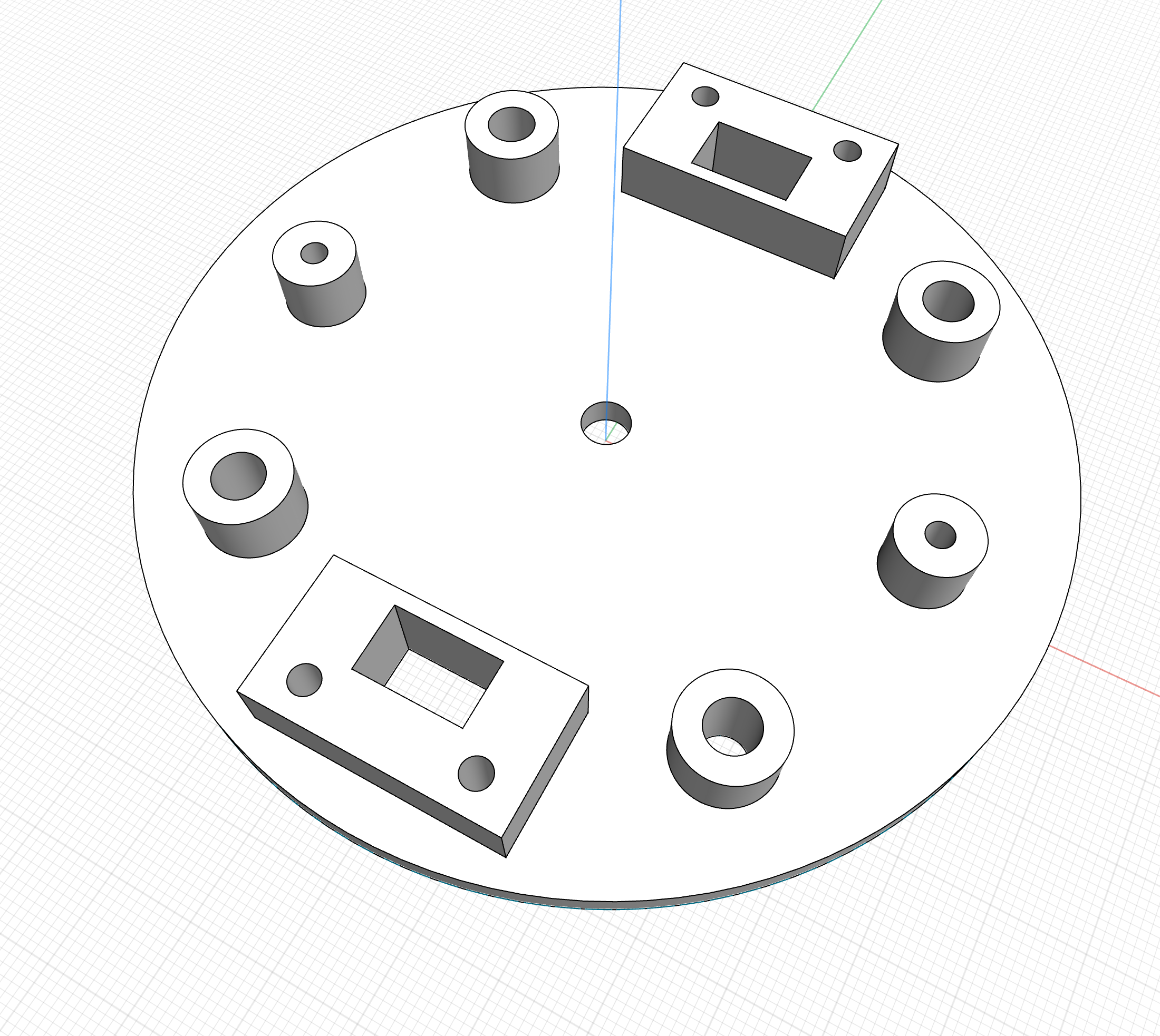
The bulkhead drilling guide is pictured below. There are four equidistant holes which will accept the thread rod, two square holes with small screw holes for the through the wall screw terminals, and two other holes 90º from the square cuts that are intended for mounting the deployment charge wells.
Both bulkheads were cut at the same time to insure that they were matched and exact copies. The aft (drogue end) bulkhead holes for the threaded rods were cut such that they could be tapped for the 1/4-20 thread rod. The forward bulkhead was cut to 1/4 inch to allow the bulkhead to slide on and off of the threaded rod. All remaining holes were tapped for their associated screws.
- 4-40 for the screws in the through the wall screw terminals and
- 8-32 for the screws that hold the ejection charge wells to the bulkheads
The following is a photo of the populated bulkhead showing the screw terminals, Rocket Junkies 3-gram aluminum charge wells, threaded rods and their securing thumbnuts.
Due to the fact that black powder — detonated to effect parachute deployment — is dirty and leaves residue on the bulkhead and its bulkhead's components, I tried something new for this build.
I 3D designed and printed a cover for the screw terminals on the bulkhead. Because I elected to used stepped thumbwheel lock nuts on my bulkhead, the step in the wheel can hold the screw terminal covers in place as well as secure the entire bulkhead assembly. These covers slide over the screw terminals allowing access for the electric match leads. This is, in my not so humble opinion, a much better solution than covering the terminals with sticky masking tape as many rocketeer will do. Detail of the screw terminal covers is pictured below.
I printed these covers in two colors — black and red. I use the red on the aft (red: rear, drogue) end of the avionics bay and the black on the forward (main) end. The avionics bay, otherwise, looks identical from both ends. When in the field at a launch, I'll easily know which end of the avionics bay mates with/into the other parts of the rocket.
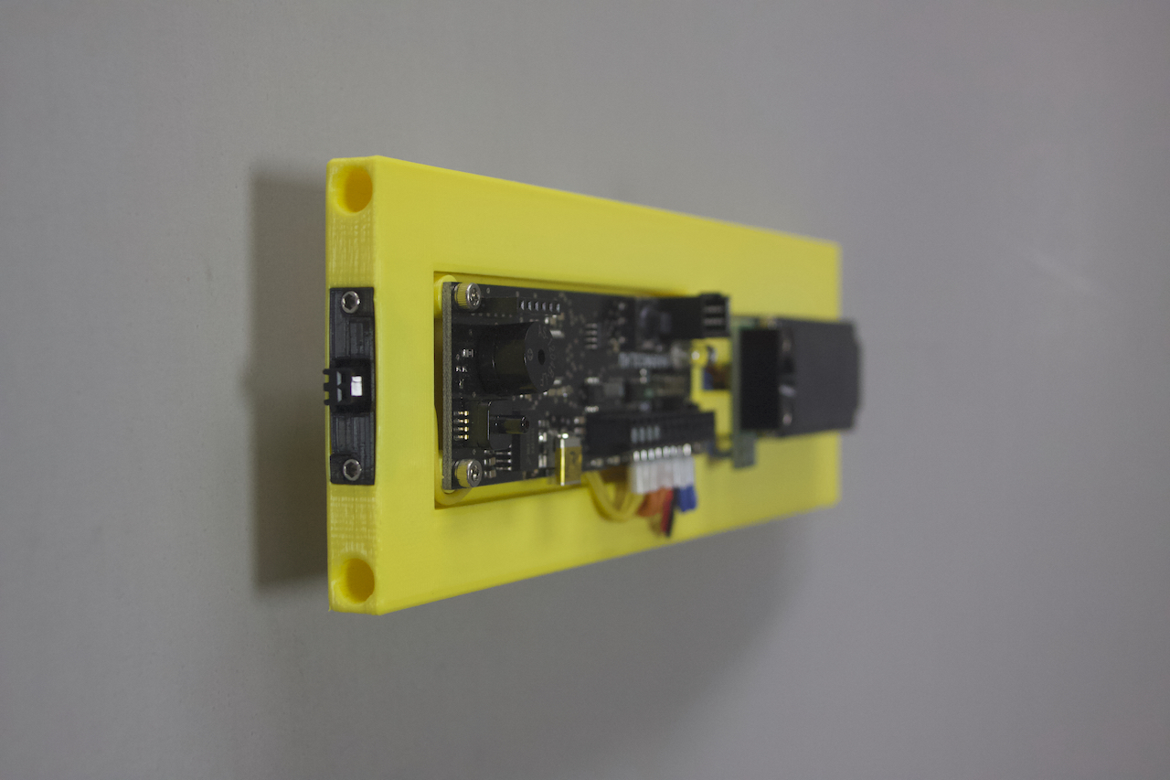
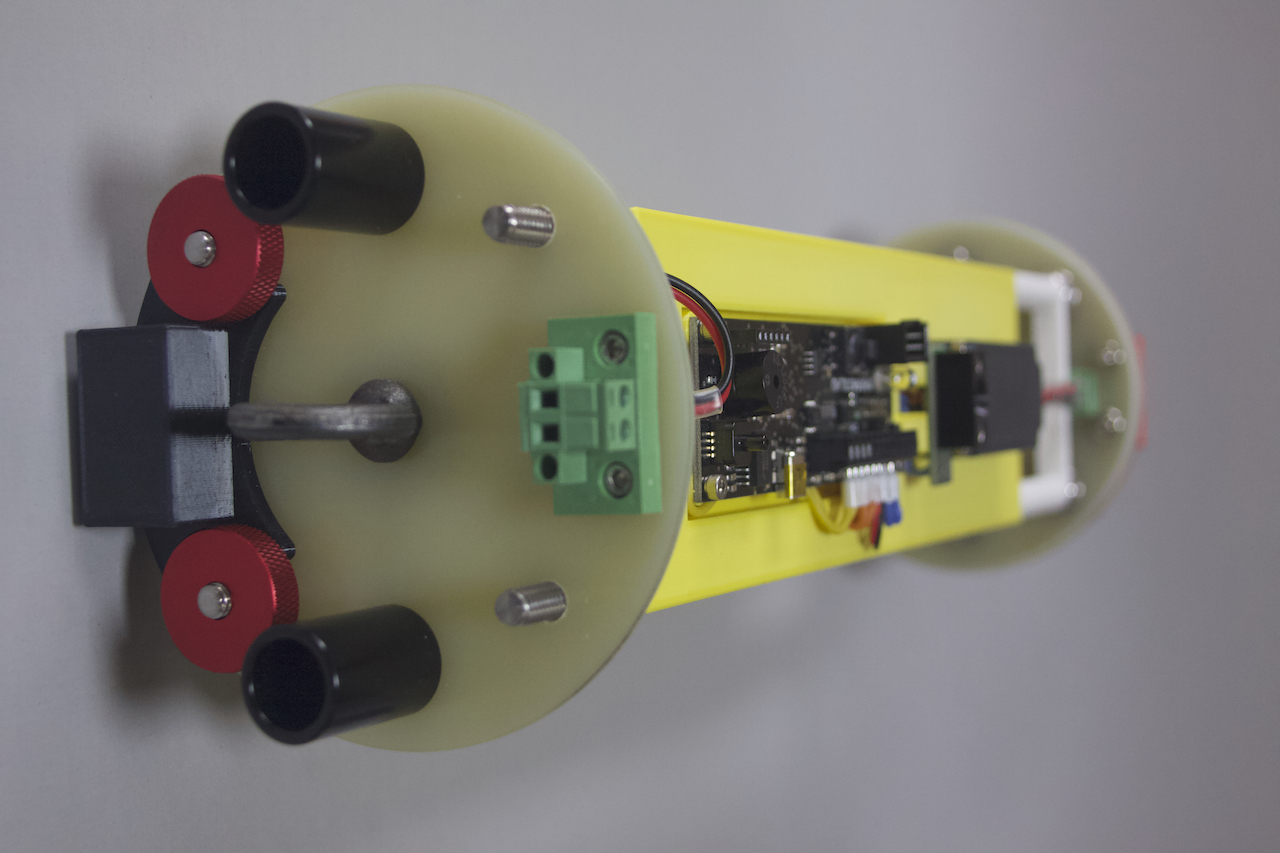
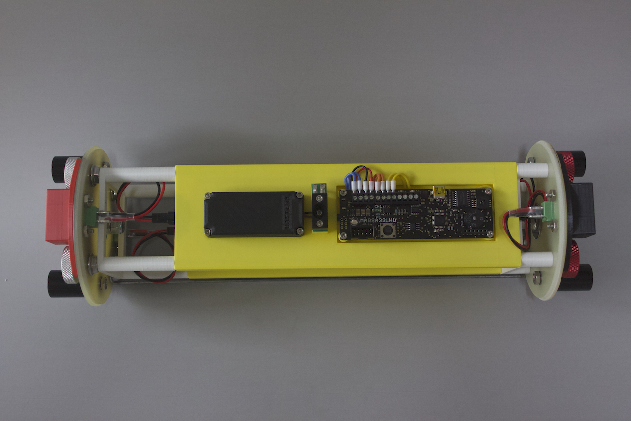
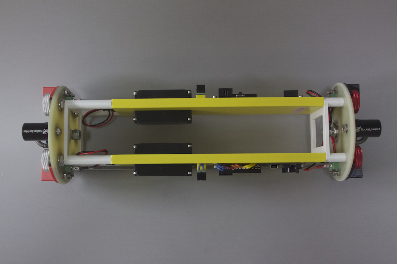
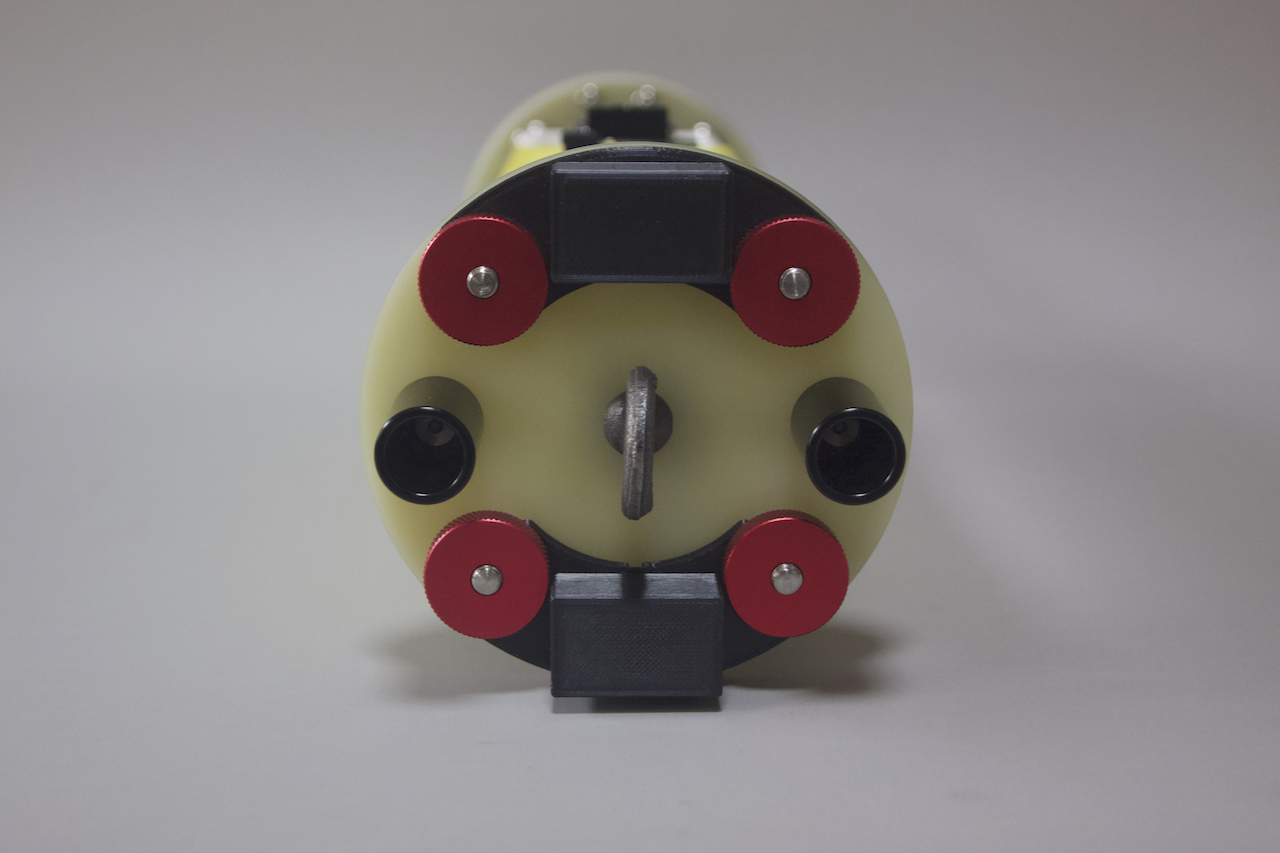
The following photos show the completed/assembled avionics bay. The white pieces are 3D printed spacers intended to keep the avionics sled properly positioned.
AVIONICS BAY BULKHEADS
With the avionics bay sled design and assembly complete, the next task to tackle was the physical avionics bay and its bulk heads.
For several years now, I have employed a proper screw terminal connector in my avionics bays, not something intended for use by house-wiring jockeys inside breaker panels. The screw terminals I use allow a through the bulkhead connection for connecting the electric matches. Properly mounted, they are air tight and they're meant for/designed for use with 20-24 gauge wire, not 14-16 gauge Romex wire. I buy my electronics components from electronics supply houses, not Home Depot. 😉 These screw connectors are also two pieces. The actual piece which houses the screw terminals plugs into a second piece that is the through the panel socket. The following image details these connectors.
For the HV-ARCAS, I settled on a redundant altimeter scheme — primary and backup. Thus, to simplify this redundancy, there are two completely independent dual-deployment systems. To accommodate two completely independent systems, I decided to employ two sets of threaded rod to tie the avionics bulkheads together. This simplifies the sled design and it offers superior strength to the avionics bay.
Once again, I employed the 3D design software on my MacBook Pro and my 3D printer. I designed the avionics bay and then, used its dimensional figures to create a 3D printed drilling guide that I used with my milling machine to create the actual fiberglass bulkheads. This simplified my efforts on the milling machine. In the past I would need precision measurement to position the quill over the material. This also meant that I needed to spend significant time tramming and squaring up the fiberglass bulkheads before performing any mill cutting. With the 3D printed guide, I could lower the quill and cutter into the cutting guide and then, secure the workpiece to the traverse table. For the square holes needed for the through the wall screw terminal connector, I placed a collar around part of the cutter and then moved the traverse table to follow the square in the drilling guide. The smallest diameter mill cutter I have is 1/8 inch, so the corners would be rounded with a radius of 1/16 inch. No problem there because I have a good set of diamond files making it a quick, simple and fast task to square the corners. Note: If you are working on/with fiberglass and you do not have a set of diamond files, you're making much work for yourself. HarborFreight has a 10-file set for $7! So cheap that you can afford a backup set or sets. HarborFreight Diamond File Set
The bulkhead drilling guide is pictured below. There are four equidistant holes which will accept the thread rod, two square holes with small screw holes for the through the wall screw terminals, and two other holes 90º from the square cuts that are intended for mounting the deployment charge wells.
Both bulkheads were cut at the same time to insure that they were matched and exact copies. The aft (drogue end) bulkhead holes for the threaded rods were cut such that they could be tapped for the 1/4-20 thread rod. The forward bulkhead was cut to 1/4 inch to allow the bulkhead to slide on and off of the threaded rod. All remaining holes were tapped for their associated screws.
- 4-40 for the screws in the through the wall screw terminals and
- 8-32 for the screws that hold the ejection charge wells to the bulkheads
The following is a photo of the populated bulkhead showing the screw terminals, Rocket Junkies 3-gram aluminum charge wells, threaded rods and their securing thumbnuts.
Due to the fact that black powder — detonated to effect parachute deployment — is dirty and leaves residue on the bulkhead and its bulkhead's components, I tried something new for this build.
I 3D designed and printed a cover for the screw terminals on the bulkhead. Because I elected to used stepped thumbwheel lock nuts on my bulkhead, the step in the wheel can hold the screw terminal covers in place as well as secure the entire bulkhead assembly. These covers slide over the screw terminals allowing access for the electric match leads. This is, in my not so humble opinion, a much better solution than covering the terminals with sticky masking tape as many rocketeer will do. Detail of the screw terminal covers is pictured below.
I printed these covers in two colors — black and red. I use the red on the aft (red: rear, drogue) end of the avionics bay and the black on the forward (main) end. The avionics bay, otherwise, looks identical from both ends. When in the field at a launch, I'll easily know which end of the avionics bay mates with/into the other parts of the rocket.
The following photos show the completed/assembled avionics bay. The white pieces are 3D printed spacers intended to keep the avionics sled properly positioned.
Quote from VAXman on January 30, 2023, 11:14 amKEVLAR TETHER MOUNT
This one's for JoAnn.
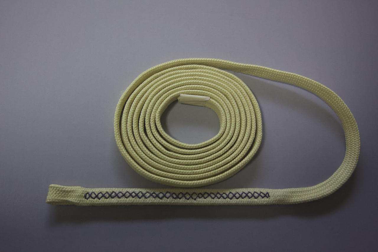
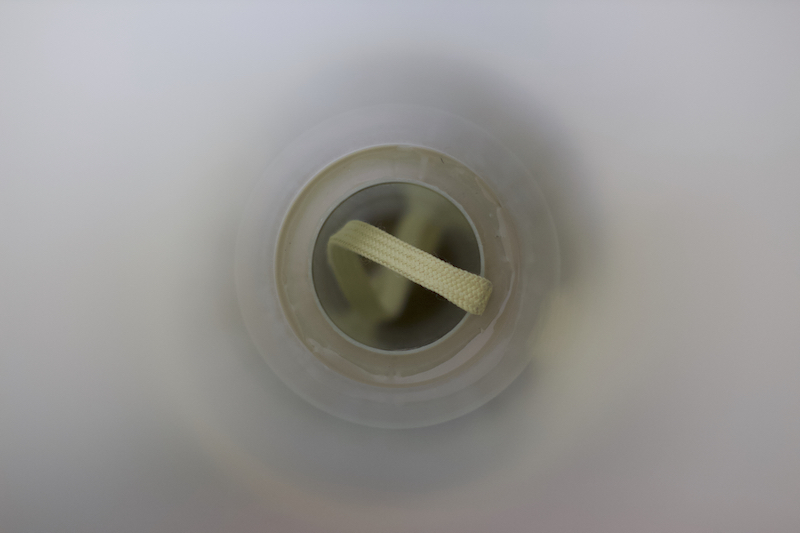
The shock cord will be attached with quick links to a kevlar harness attached to the motor mount tube (MMT). For this application, I have a 10 foot length of 9/16 inch tubular kevlar. About 16" of this length will be epoxied to the MMT. The other end is fashioned into a loop whereby additional length of shock cord can be attached with a quick-link.
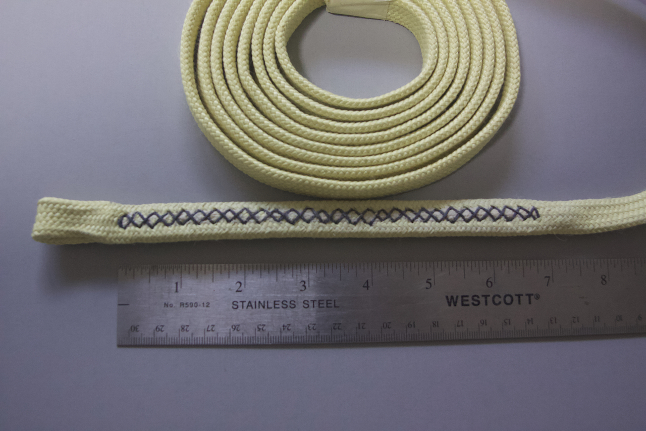
The loop was effected by back weaving approximately 8 inches of the kevlar through itself. The friction alone is sufficient to keep the loop secure but it needs to be better secured with stitching. Approximately 7 inches of the length of the back weave is stitched with 100 lbs. kevlar thread using a SpeedyStitcher. I marked the stitch puncture locations on a piece of masking tape and then, applied the tape to the back weave section of the kevlar. The SpeedyStitcher was threaded with the 100 lbs. kevlar thread (approximately, .8mm diameter thread). Then, meticulously as possible, the SpeedyStitcher's awl is pushed through the tubular kevlar. There are several YouTube videos on how to sew kevlar with a SpeedyStitcher if you are interested. I, personally, prefer to back weave the kevlar and then, stitch it whereas others just fold it over and sew.
The following is a photo of the full 10 feet of the kevlar tether.
This image shows the detail of the sewn portion of the kevlar to effect the attachment loop.
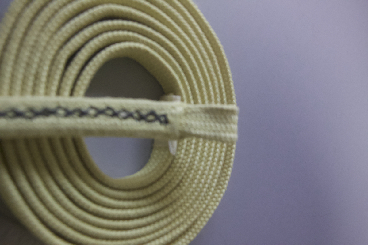
Detail of the back weave. Sorry about the focus; I need a macro lens and I have not yet acquired one.
KEVLAR TETHER MOUNT
This one's for JoAnn.
The shock cord will be attached with quick links to a kevlar harness attached to the motor mount tube (MMT). For this application, I have a 10 foot length of 9/16 inch tubular kevlar. About 16" of this length will be epoxied to the MMT. The other end is fashioned into a loop whereby additional length of shock cord can be attached with a quick-link.
The loop was effected by back weaving approximately 8 inches of the kevlar through itself. The friction alone is sufficient to keep the loop secure but it needs to be better secured with stitching. Approximately 7 inches of the length of the back weave is stitched with 100 lbs. kevlar thread using a SpeedyStitcher. I marked the stitch puncture locations on a piece of masking tape and then, applied the tape to the back weave section of the kevlar. The SpeedyStitcher was threaded with the 100 lbs. kevlar thread (approximately, .8mm diameter thread). Then, meticulously as possible, the SpeedyStitcher's awl is pushed through the tubular kevlar. There are several YouTube videos on how to sew kevlar with a SpeedyStitcher if you are interested. I, personally, prefer to back weave the kevlar and then, stitch it whereas others just fold it over and sew.
The following is a photo of the full 10 feet of the kevlar tether.
This image shows the detail of the sewn portion of the kevlar to effect the attachment loop.
Detail of the back weave. Sorry about the focus; I need a macro lens and I have not yet acquired one.
Quote from VAXman on January 30, 2023, 5:48 pmQuote from Zielijo1 on January 30, 2023, 4:14 pmSweet. Can’t wait to see it roar off the pad
Red Glare! I need to get a 10inch diamond blade for the new table saw so that I can cut a 1/2 high ring off of the nose cone coupler tube to make an internal thrust ring in the booster. Next trek in the vicinity of Lowes. I only hope I have a relatively nice day to do it outside. The fiberglass dust is a bugger to clean up.
Quote from Zielijo1 on January 30, 2023, 4:14 pmSweet. Can’t wait to see it roar off the pad
Red Glare! I need to get a 10inch diamond blade for the new table saw so that I can cut a 1/2 high ring off of the nose cone coupler tube to make an internal thrust ring in the booster. Next trek in the vicinity of Lowes. I only hope I have a relatively nice day to do it outside. The fiberglass dust is a bugger to clean up.
Quote from VAXman on February 15, 2023, 11:56 amSome more progress to report on my HV-ARCAS. Things have been slow going due to dealing with sleazy Geico insurance company for an auto accident, mother's upcoming surgeries, father-in-law's water heater, playing chauffeur to all because two cars are now out of commission, etc., etc., etc. "Life is what happens to you while you're busy making other plans." — John Lennon from: Beautiful Boy (Darling Boy)
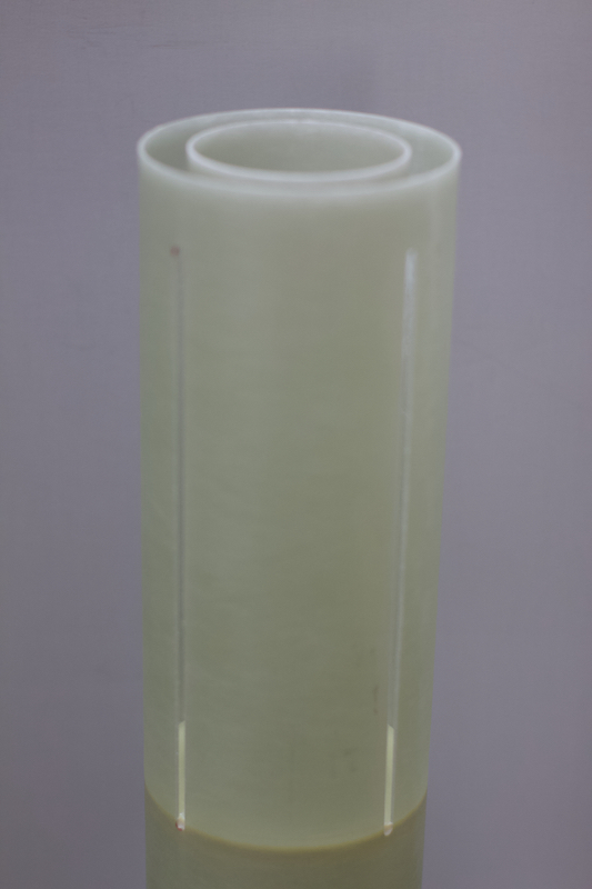
Due to the odd size of the ARCAS (4.5in diameter) there were no commercially available aluminum thrust plates available. Therefore, I needed to use the lower centering ring (CR) as the thrust plate. To insure energy transfer to the entire airframe, I cut a 7/8 inch ring of fiberglass from the nosecone's coupler. There's ample coupler for the nosecone, so this small length will not affect it. This ring will allow the CR to have a seat when placed into the end of the airframe. This ring will have much more epoxy surface for added strength than just epoxying the edge of the CR in the airframe. The lower edge of the rocket's fins will sit directly at the top edge of the thrust ring as well to insure an even better transfer of the motor energy throughout the airframe.
The MMT is now mounted in the booster airframe. I forgot to get a photo of the kevlar harness mounted to the MMT before the MMT was epoxied in the booster. The kevlar, 16 inches of it, was epoxied (RocketPoxy) to the side of the MMT. Two of the centering rings (CRs) were notched out to fit over the kevlar. One CR is mounted at the forward end of the MMT and the second CR placed such that the fins will abut to it. A spacer was 3D printed to allow the forward CR to be epoxied to the MMT perfectly normal/square to the end 10mm back from the edge.
The second CR was then positioned and epoxied to the MMT such that it would be at the top edge of the fins when they are installed into the airframe. This CR was held parallel to the forward CR with a clamp and the epoxy applied. Again, I should have captured an image of this before it was put into the airframe.
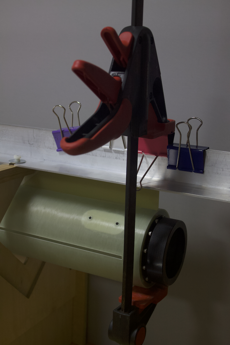
This is a view of the MMT in the boost airframe.
This is a view of the upper CR epoxied to the airframe. That CR is 32 inches from the top edge of the boost airframe tube.
Now, you may be asking, "How did I get the epoxy all the way down there?"
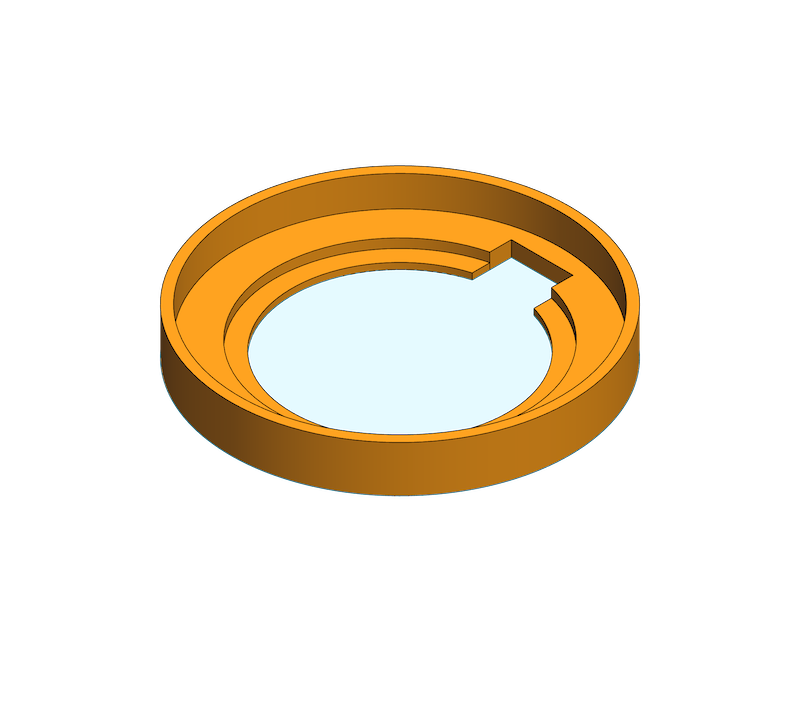
With the aid of the motor retainer and thrust plate and thrust ring, I 3D printed a 12mm × high 83.2mm diameter with a 6.4mm hole to accept a 1/4-20 bolt. This was placed in the motor retainer. The bolt was then put into the chuck of my largest (1/2 chuck) hand drill to allow me to spin the entire assemble of the MMT and airframe. RocketPoxy (~12g) was mixed and then carefully applied to the surfaces of the two CRs making certain that none got on the edges of the CRs. This assembly was then inserted into the booster airframe. The bolt was placed into the chuck of the drill. The entire assembly could now be spun causing the RocketPoxy to be flung outward against the booster airframe. The bolt was de-chucked and the motor retainer/thrust-plate/thrust-ring assembly removed. Because of the design, the bottom of the MMT is aligned with the bottom of the airframe, so the entire assembly was set aside on its end. The epoxy now flows from the walls of the airframe down along the CRs for a smooth epoxy finish. Before the RocketPoxy cures too much, the MMT assembly is moved slightly up and down to get epoxy along the edge of the CRs and the airframe.
Some more progress to report on my HV-ARCAS. Things have been slow going due to dealing with sleazy Geico insurance company for an auto accident, mother's upcoming surgeries, father-in-law's water heater, playing chauffeur to all because two cars are now out of commission, etc., etc., etc. "Life is what happens to you while you're busy making other plans." — John Lennon from: Beautiful Boy (Darling Boy)
Due to the odd size of the ARCAS (4.5in diameter) there were no commercially available aluminum thrust plates available. Therefore, I needed to use the lower centering ring (CR) as the thrust plate. To insure energy transfer to the entire airframe, I cut a 7/8 inch ring of fiberglass from the nosecone's coupler. There's ample coupler for the nosecone, so this small length will not affect it. This ring will allow the CR to have a seat when placed into the end of the airframe. This ring will have much more epoxy surface for added strength than just epoxying the edge of the CR in the airframe. The lower edge of the rocket's fins will sit directly at the top edge of the thrust ring as well to insure an even better transfer of the motor energy throughout the airframe.
The MMT is now mounted in the booster airframe. I forgot to get a photo of the kevlar harness mounted to the MMT before the MMT was epoxied in the booster. The kevlar, 16 inches of it, was epoxied (RocketPoxy) to the side of the MMT. Two of the centering rings (CRs) were notched out to fit over the kevlar. One CR is mounted at the forward end of the MMT and the second CR placed such that the fins will abut to it. A spacer was 3D printed to allow the forward CR to be epoxied to the MMT perfectly normal/square to the end 10mm back from the edge.
The second CR was then positioned and epoxied to the MMT such that it would be at the top edge of the fins when they are installed into the airframe. This CR was held parallel to the forward CR with a clamp and the epoxy applied. Again, I should have captured an image of this before it was put into the airframe.
This is a view of the MMT in the boost airframe.
This is a view of the upper CR epoxied to the airframe. That CR is 32 inches from the top edge of the boost airframe tube.
Now, you may be asking, "How did I get the epoxy all the way down there?"
With the aid of the motor retainer and thrust plate and thrust ring, I 3D printed a 12mm × high 83.2mm diameter with a 6.4mm hole to accept a 1/4-20 bolt. This was placed in the motor retainer. The bolt was then put into the chuck of my largest (1/2 chuck) hand drill to allow me to spin the entire assemble of the MMT and airframe. RocketPoxy (~12g) was mixed and then carefully applied to the surfaces of the two CRs making certain that none got on the edges of the CRs. This assembly was then inserted into the booster airframe. The bolt was placed into the chuck of the drill. The entire assembly could now be spun causing the RocketPoxy to be flung outward against the booster airframe. The bolt was de-chucked and the motor retainer/thrust-plate/thrust-ring assembly removed. Because of the design, the bottom of the MMT is aligned with the bottom of the airframe, so the entire assembly was set aside on its end. The epoxy now flows from the walls of the airframe down along the CRs for a smooth epoxy finish. Before the RocketPoxy cures too much, the MMT assembly is moved slightly up and down to get epoxy along the edge of the CRs and the airframe.
Quote from VAXman on February 22, 2023, 11:04 amDiamonds are a high powered rocketeer's best friend!
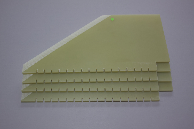
It's finally time to attach the ARCAS's fins. Yesterday, because the temperatures peaked into the 50ºF range just before the rain began, I pulled out the table saw and cut binding slits along the root edge of each fin. To speed up the process, all four fins were stacked and the outer edges taped with 2-inch wide masking tape. This was coupled with several large binder clips to act as clamps to keep all four of the fins bound tightly together. Slits where then cut in the root edges at ½ inch intervals approximately ¼ inch deep. Amazingly, the continuous diamond tile saw blade cuts through the fiberglass, even four fins stacked to a thickness of ¾ of an inch, like a hot knife through butter! These slits will give the fins more mechanical interface with the epoxy bonding to the MMT.
I also added PML (Public Missiles Ltd) 1515 linear rail guides to the booster's airframe. One that is about 1-inch from the aft edge of the booster airframe and the second positioned with sufficient clearance for the av-bay at the upper/forward edge of the booster airframe.
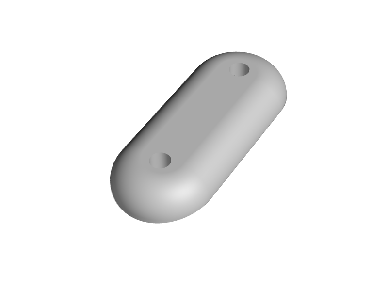
The airframe fiberglass wall is too thin to tap and expect the forces of a launch to hold the rail guide to the airframe. To add more strength/support for the screws, stainless steel threaded inserts backup the screw holes. This provides a good deal of strength but introduces another problem; that is, having the recovery laundry catch on the protruding screws and inserts. This problem is addressed with a backing plate for the linear rail guides. The threaded inserts are inserted into this backing plate and the entire assembly is epoxied into the airframe. The edges of the backing plate are chamfered to the airframe surface making it a smoother impediment during deployment of the parachute (the drogue parachute in this case).
Diamonds are a high powered rocketeer's best friend!
It's finally time to attach the ARCAS's fins. Yesterday, because the temperatures peaked into the 50ºF range just before the rain began, I pulled out the table saw and cut binding slits along the root edge of each fin. To speed up the process, all four fins were stacked and the outer edges taped with 2-inch wide masking tape. This was coupled with several large binder clips to act as clamps to keep all four of the fins bound tightly together. Slits where then cut in the root edges at ½ inch intervals approximately ¼ inch deep. Amazingly, the continuous diamond tile saw blade cuts through the fiberglass, even four fins stacked to a thickness of ¾ of an inch, like a hot knife through butter! These slits will give the fins more mechanical interface with the epoxy bonding to the MMT.
I also added PML (Public Missiles Ltd) 1515 linear rail guides to the booster's airframe. One that is about 1-inch from the aft edge of the booster airframe and the second positioned with sufficient clearance for the av-bay at the upper/forward edge of the booster airframe.
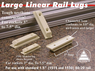
The airframe fiberglass wall is too thin to tap and expect the forces of a launch to hold the rail guide to the airframe. To add more strength/support for the screws, stainless steel threaded inserts backup the screw holes. This provides a good deal of strength but introduces another problem; that is, having the recovery laundry catch on the protruding screws and inserts. This problem is addressed with a backing plate for the linear rail guides. The threaded inserts are inserted into this backing plate and the entire assembly is epoxied into the airframe. The edges of the backing plate are chamfered to the airframe surface making it a smoother impediment during deployment of the parachute (the drogue parachute in this case).
Quote from VAXman on March 7, 2023, 3:17 pmFins have been attached. Like most high power rockets, this has TTW (through the wall) fin construction. The fins pass through a slot in the airframe and are bonded to the MMT (motor mount tube). The fins, as can be seen in a previous post, had been slotted along the root edge to add more surface area for the epoxy to adhere. This is a photo of the fin bonded to the MMT and the effect of the slots across the root edge.
I have two Maklin fin jigs. A small one for rockets from approximately 1.5 inch in diameter to 4 inches in diameter. The second is bigger and can accommodate rockets up to 6.5 inches in diameter. For the ARCAS, I used the larger Maklin jig. This is a photo of how the fins are setup and clamped in the jig to insure that they are normal to the airframe.
When all four fins have been bonded, I will go back an add internal fillets along both sides of each fin at the MMT interface and the airframe interface.
Fins have been attached. Like most high power rockets, this has TTW (through the wall) fin construction. The fins pass through a slot in the airframe and are bonded to the MMT (motor mount tube). The fins, as can be seen in a previous post, had been slotted along the root edge to add more surface area for the epoxy to adhere. This is a photo of the fin bonded to the MMT and the effect of the slots across the root edge.
I have two Maklin fin jigs. A small one for rockets from approximately 1.5 inch in diameter to 4 inches in diameter. The second is bigger and can accommodate rockets up to 6.5 inches in diameter. For the ARCAS, I used the larger Maklin jig. This is a photo of how the fins are setup and clamped in the jig to insure that they are normal to the airframe.
When all four fins have been bonded, I will go back an add internal fillets along both sides of each fin at the MMT interface and the airframe interface.