
The 1—6 Launch Controller

Quote from Admin on September 12, 2026, 10:58 amSome time ago, I took the 7—12 launch controller home to replace its LEDs with high-intensity LEDs for better visibility in the bright sun on the field. When I got it home and opened it up, there was enough bathtub caulk smothering everything inside to fill all of the cracks in the Thermae Bath Spa in Bath, Somerset, UK. (side note: an interesting historic visit if you're ever in the UK and it's close to Stonehenge which is a must see too.) When I'd finally clean out all of the caulk, I replaced all of the LEDs as well as the 110V sockets at the rear of the unit. Very little of the wiring was soldered together either. One large bundle was simply secured with a house wiring wire nut. 🙄
The 1—6 launch controller has been problematic lately, so I offered to clean that unit up too. On Wednesday, I met Charlie and Eric for lunch where I received the 1—6 Launch Controller from Charlie and some High Power rocket motors that Eric transported from METRA for me.
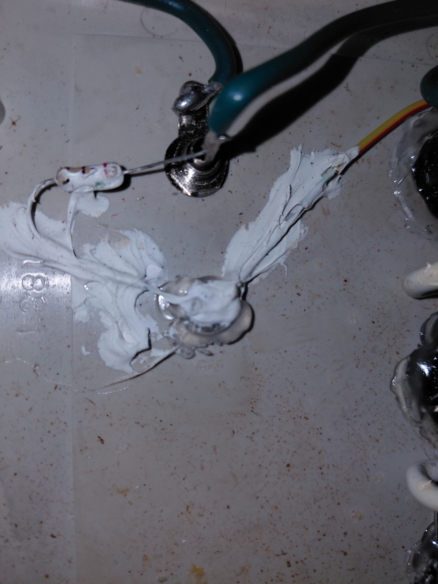
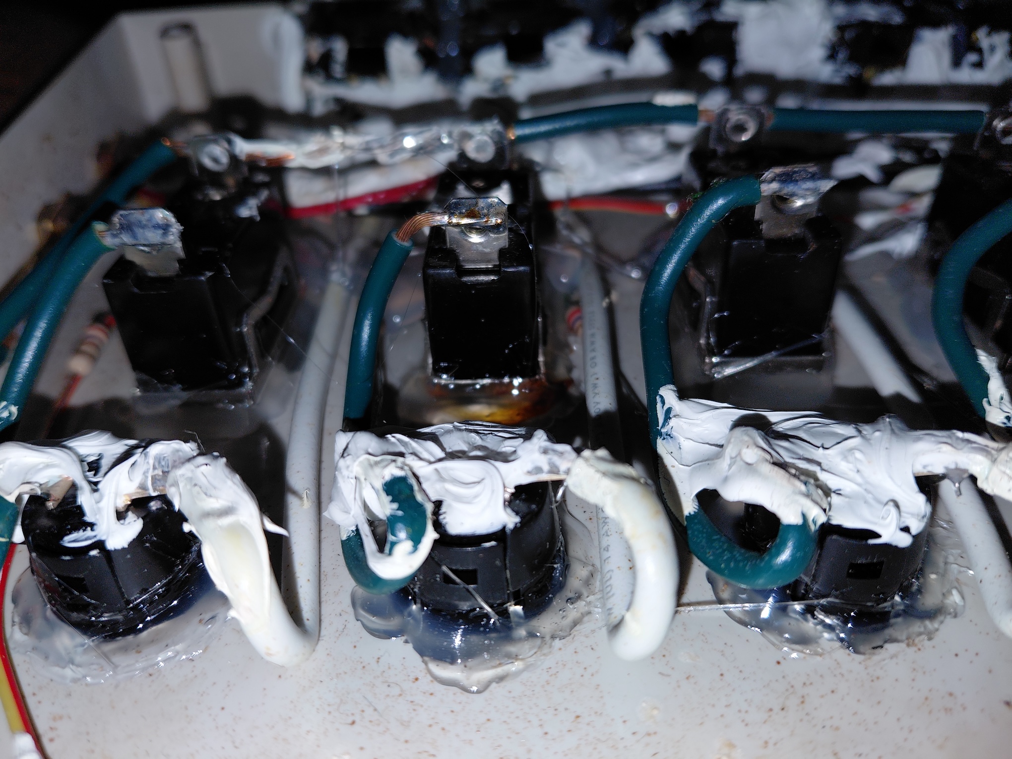
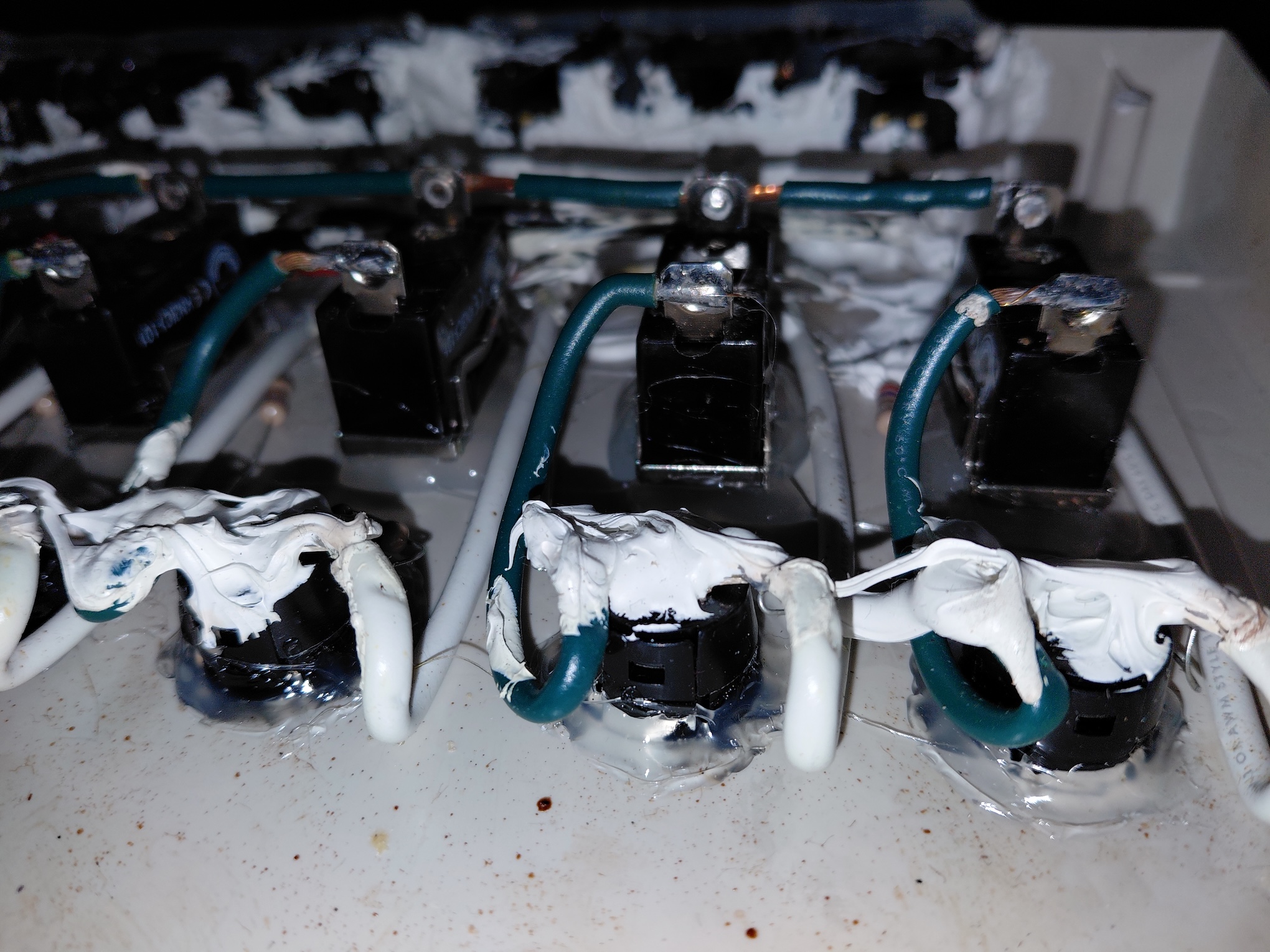
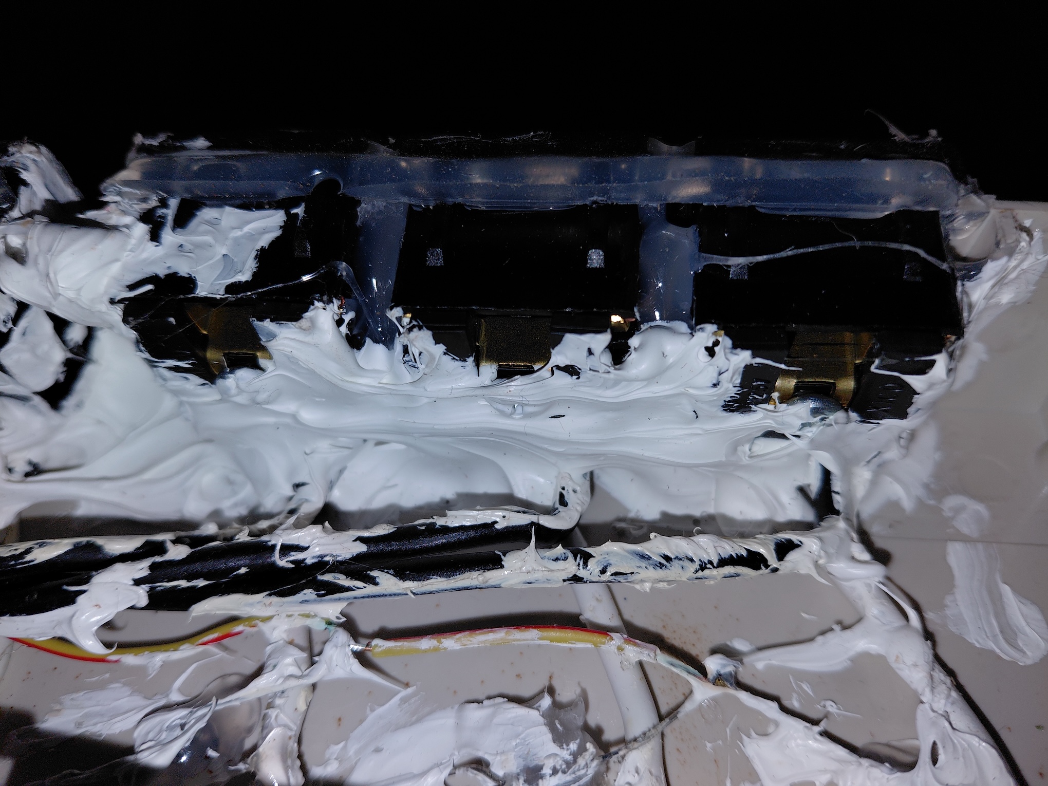
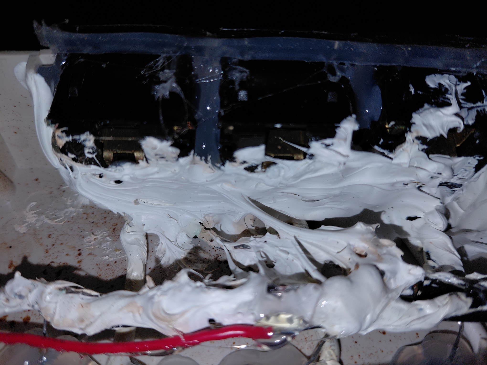
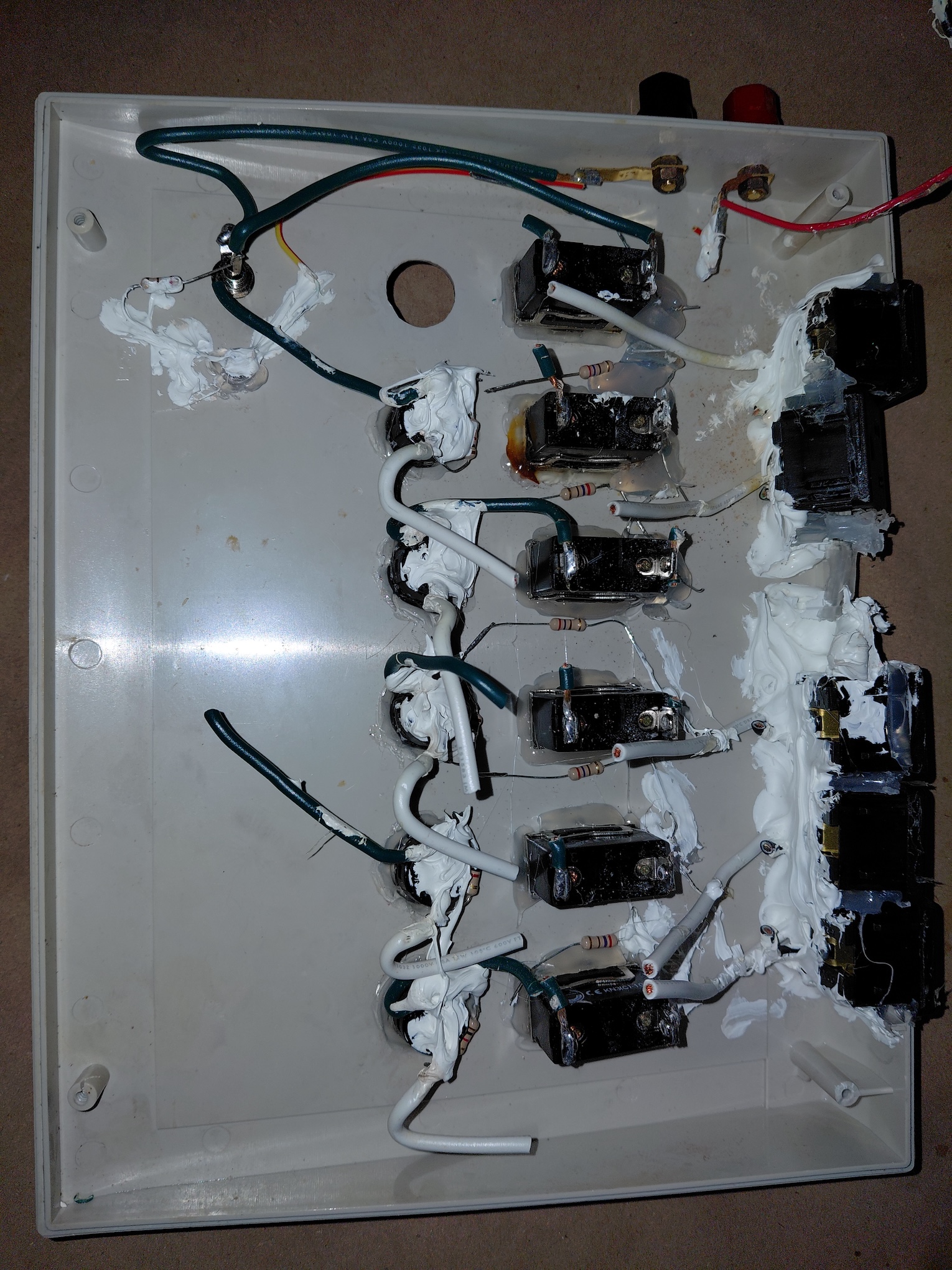
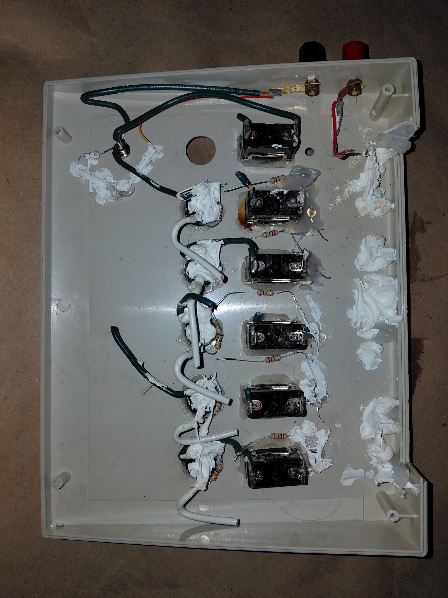
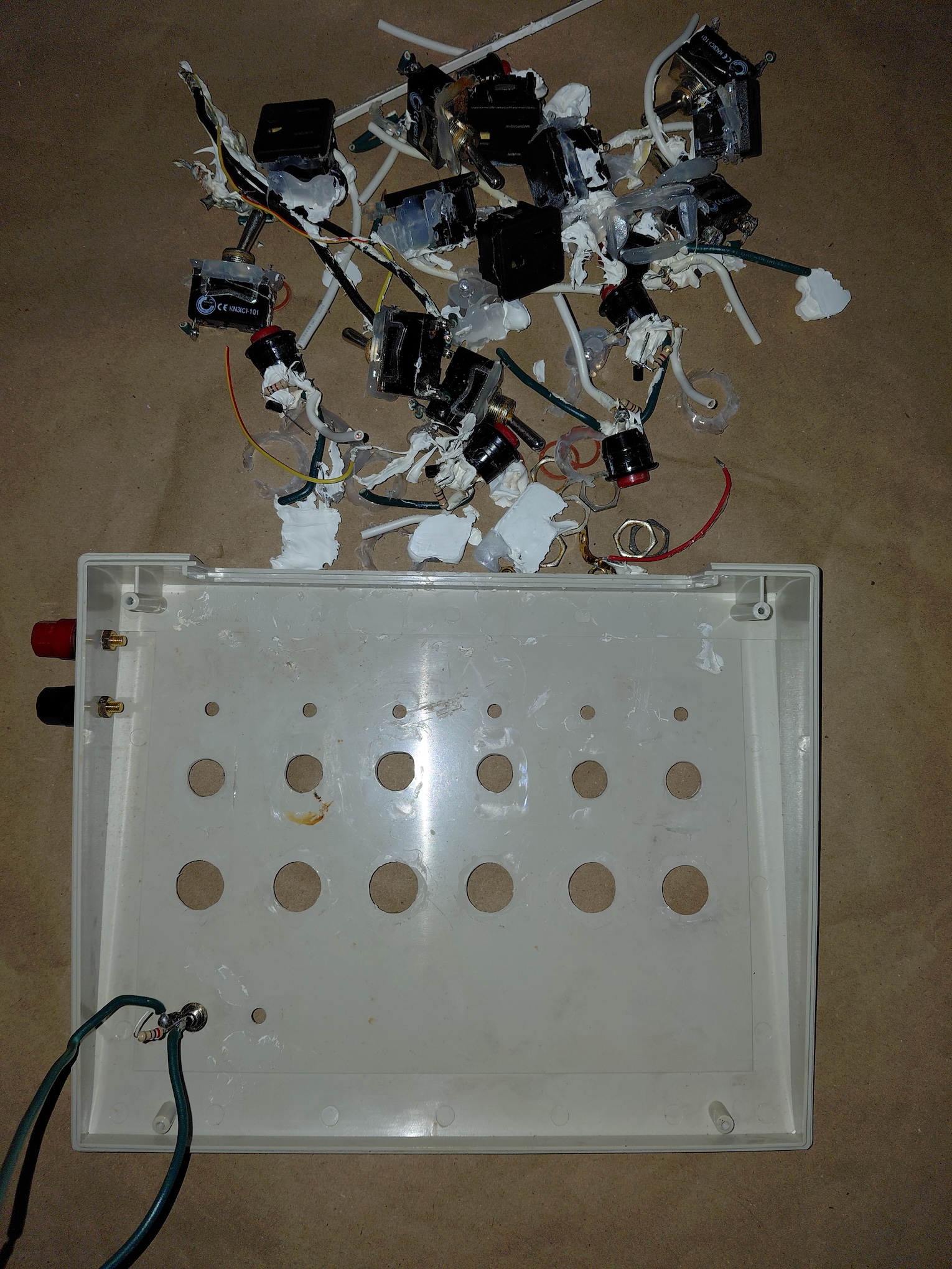
When home, I opened up the unit and it too had bathtub caulk but not as extreme as I'd found in the 7-12 unit. I've included photos below.
On thing not found in the 7—12 controller was a 2N2222A transistor circuit across each of the push-button launch switches. What's the purpose of this? There were no resistors in the circuit biasing it, so the transistor is simply operating as a low-current switch for the continuity LED. It's basically biased to work in cutoff (off) or saturation (on) modes and is bypassed completely when the launch switch is pressed. This seems to me to be completely unnecessary for our use. If the launch pad leads were hundreds of feet away, the wire resistance could be too high to cause the continuity LED to light. That'd be quite a resistive drop for a device that only needs a forward voltage of 2 to 4 volts (color dependent) to light. The hFE (current gain) of the 2N2222A is between 150 and 300 which means that only a few milliamps could switch the transistor. For our uses, perhaps 100 feet, there's no need for such a solid-state switch. I will be wiring the unit like the 7—12 unit and, if it's deemed necessary, I can introduce a similar transistor switch easily.
I ordered up some marine toggle switches which should hold up better in the environments where we launch than the HD toggle switches that were in the unit. I also needed to order up new push-button momentary-contact switches that would fit the large holes drilled for the original switches. I wanted to purchase tactile switches but I could not find any in the large diameter format.
I should have all parts today and I'll be soldering tomorrow. The 1—6 unit will be ready for next weekend's Kids Day at the Wall Township Municipal complex.
Some time ago, I took the 7—12 launch controller home to replace its LEDs with high-intensity LEDs for better visibility in the bright sun on the field. When I got it home and opened it up, there was enough bathtub caulk smothering everything inside to fill all of the cracks in the Thermae Bath Spa in Bath, Somerset, UK. (side note: an interesting historic visit if you're ever in the UK and it's close to Stonehenge which is a must see too.) When I'd finally clean out all of the caulk, I replaced all of the LEDs as well as the 110V sockets at the rear of the unit. Very little of the wiring was soldered together either. One large bundle was simply secured with a house wiring wire nut. 🙄
The 1—6 launch controller has been problematic lately, so I offered to clean that unit up too. On Wednesday, I met Charlie and Eric for lunch where I received the 1—6 Launch Controller from Charlie and some High Power rocket motors that Eric transported from METRA for me.
When home, I opened up the unit and it too had bathtub caulk but not as extreme as I'd found in the 7-12 unit. I've included photos below.
On thing not found in the 7—12 controller was a 2N2222A transistor circuit across each of the push-button launch switches. What's the purpose of this? There were no resistors in the circuit biasing it, so the transistor is simply operating as a low-current switch for the continuity LED. It's basically biased to work in cutoff (off) or saturation (on) modes and is bypassed completely when the launch switch is pressed. This seems to me to be completely unnecessary for our use. If the launch pad leads were hundreds of feet away, the wire resistance could be too high to cause the continuity LED to light. That'd be quite a resistive drop for a device that only needs a forward voltage of 2 to 4 volts (color dependent) to light. The hFE (current gain) of the 2N2222A is between 150 and 300 which means that only a few milliamps could switch the transistor. For our uses, perhaps 100 feet, there's no need for such a solid-state switch. I will be wiring the unit like the 7—12 unit and, if it's deemed necessary, I can introduce a similar transistor switch easily.
I ordered up some marine toggle switches which should hold up better in the environments where we launch than the HD toggle switches that were in the unit. I also needed to order up new push-button momentary-contact switches that would fit the large holes drilled for the original switches. I wanted to purchase tactile switches but I could not find any in the large diameter format.
I should have all parts today and I'll be soldering tomorrow. The 1—6 unit will be ready for next weekend's Kids Day at the Wall Township Municipal complex.
Uploaded files: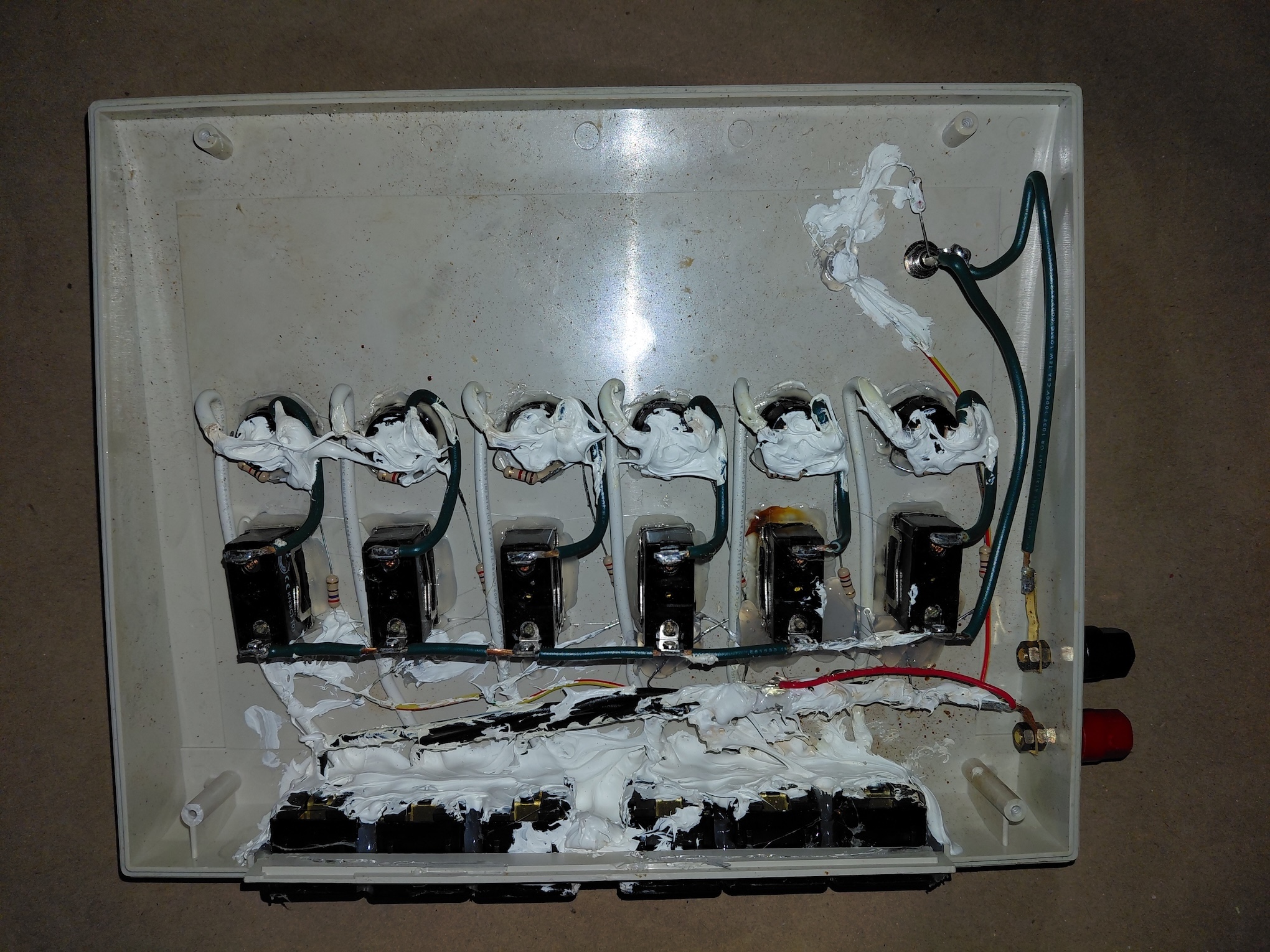
Quote from Admin on September 16, 2026, 7:07 pmWell, it's time to unveil the revamping of the 1—6 launch controller. I would have preferred a using other options for the switches for the rework but the original hole diameters drilled by Pratt were for his components collected from his favorite electronics supply company — Home Depot — and I had to opt for switches from real electronic component supplies that would fit those holes.
I also fixed the cheap plastic case for the launch controller that was damaged either by over-turning the screws or simply from manhandling the units. I replaced everything inside — the toggle switches, the push button switches, the LEDs, the banana plug jacks for power, and even the cheese RCA jack that serves as the power enable key. When I was looking for replacement switches for the launch buttons, I found colors buttons. Because this 1–6 launch controller is ofter manned by youthful rocketeers wanting to launch their rockets, colors buttons adds an additional descriptive for the young pushers of buttons.
I had intended to put a bridge rectifier comprised of 30SQ050 (30A,50V) Schottky diodes which have a forward voltage drop of .35V. In a bridge rectifier configuration, the maximum voltage drop would be .7V. Doing this would insure that the controller could still function even if connected improperly to the battery. However, I decided to only use a single diode to protect the circuity from incorrect polarity.
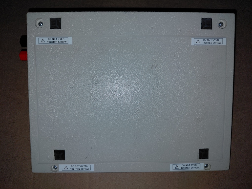
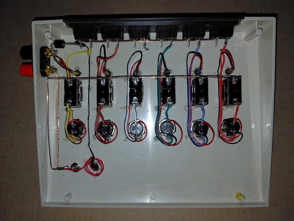
Everything inside is soldered. Major power carrying parts of the circuit are handled by solid copper busbar. All wiring was tacked in place with some dabs of hot glue. I also 3D printed the rear apron in black ASA for the 110v AC sockets used to connect the leads to the launch pads.
NO BATHTUB CAULK!!!
Well, it's time to unveil the revamping of the 1—6 launch controller. I would have preferred a using other options for the switches for the rework but the original hole diameters drilled by Pratt were for his components collected from his favorite electronics supply company — Home Depot — and I had to opt for switches from real electronic component supplies that would fit those holes.
I also fixed the cheap plastic case for the launch controller that was damaged either by over-turning the screws or simply from manhandling the units. I replaced everything inside — the toggle switches, the push button switches, the LEDs, the banana plug jacks for power, and even the cheese RCA jack that serves as the power enable key. When I was looking for replacement switches for the launch buttons, I found colors buttons. Because this 1–6 launch controller is ofter manned by youthful rocketeers wanting to launch their rockets, colors buttons adds an additional descriptive for the young pushers of buttons.
I had intended to put a bridge rectifier comprised of 30SQ050 (30A,50V) Schottky diodes which have a forward voltage drop of .35V. In a bridge rectifier configuration, the maximum voltage drop would be .7V. Doing this would insure that the controller could still function even if connected improperly to the battery. However, I decided to only use a single diode to protect the circuity from incorrect polarity.
Everything inside is soldered. Major power carrying parts of the circuit are handled by solid copper busbar. All wiring was tacked in place with some dabs of hot glue. I also 3D printed the rear apron in black ASA for the 110v AC sockets used to connect the leads to the launch pads.
NO BATHTUB CAULK!!!
Uploaded files: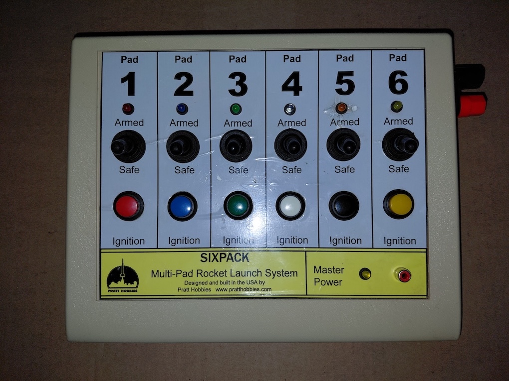

Quote from Ckirlew on September 16, 2026, 7:56 pmWow! That looks very professional! I wouldn't expect anything less.
Wow! That looks very professional! I wouldn't expect anything less.

Quote from Eric Becher on September 16, 2026, 8:27 pmNice!!
I like the colored buttons... and the lights look like they match the buttons too!
Now we'll have to paint the racks and rods to match those colors. 😃
Looking forward to testing it out on Saturday at the Wall kid's day event.
Nice!!
I like the colored buttons... and the lights look like they match the buttons too!
Now we'll have to paint the racks and rods to match those colors. 😃
Looking forward to testing it out on Saturday at the Wall kid's day event.
Quote from Admin on September 17, 2026, 6:31 amGood observation! Yes, the LEDs do match the buttons save for the black. I tried to find a black light LED and a few Spencer's Gifts Velvet Elvis posters but couldn't, so I used orange for that one. I do have IR and UV LEDs but none of us can see those color frequencies. Also, and it's not evident in the photos, I used a flashing yellow LED for the power indicator. Too many times we leave the launch controller hot when it should have been made cold. I thought that a flashing LED might make that a bit more obvious.
I soldered the coaxial cable that is connected to the RCA plug "key" and I put shrink tubing over an area that had insulation damage and had been covered with icky-sticky black tape.
I also soldered a new alligator clip, with teeth, on the #1 pair replacing the Estes-style flat jaw clip that had been crimped on the wire.
Charlie handed me the cabling along with the launch controller. I added more tape (white electrical tape) over the taped regions of the cable. I also added a small Velcro strap to the "tentacle" end of the cable. With that, we can bundle the tentacles together with hopes of keeping entanglement minimized.
Martha and I need to be at our house in Wood Ridge today and we have a meeting IJ's video production crew. We probably won't get home until late evening. If I'm not encumbered with other tasks on Friday, I'll clean all of the alligator clips for Saturday's Kids Day.
Have all of the batteries well charged! Which reminds me, I created a new banana plug power cable with female spade connectors that attach to the battery lugs. All of the connectors I used are either gold plated or high brass to provide better electrical continuity and ward off oxidation.
Good observation! Yes, the LEDs do match the buttons save for the black. I tried to find a black light LED and a few Spencer's Gifts Velvet Elvis posters but couldn't, so I used orange for that one. I do have IR and UV LEDs but none of us can see those color frequencies. Also, and it's not evident in the photos, I used a flashing yellow LED for the power indicator. Too many times we leave the launch controller hot when it should have been made cold. I thought that a flashing LED might make that a bit more obvious.
I soldered the coaxial cable that is connected to the RCA plug "key" and I put shrink tubing over an area that had insulation damage and had been covered with icky-sticky black tape.
I also soldered a new alligator clip, with teeth, on the #1 pair replacing the Estes-style flat jaw clip that had been crimped on the wire.
Charlie handed me the cabling along with the launch controller. I added more tape (white electrical tape) over the taped regions of the cable. I also added a small Velcro strap to the "tentacle" end of the cable. With that, we can bundle the tentacles together with hopes of keeping entanglement minimized.
Martha and I need to be at our house in Wood Ridge today and we have a meeting IJ's video production crew. We probably won't get home until late evening. If I'm not encumbered with other tasks on Friday, I'll clean all of the alligator clips for Saturday's Kids Day.
Have all of the batteries well charged! Which reminds me, I created a new banana plug power cable with female spade connectors that attach to the battery lugs. All of the connectors I used are either gold plated or high brass to provide better electrical continuity and ward off oxidation.